1 (edited by utz 2023-10-07 08:26:42)

Topic: Tutorial: How to Write a 1-Bit Music Routine

Hiya folks, in this tutorial I'm going explain how you can write your own multi-channel music routines for 1-bit devices. If you have any questions or suggestions, feel free to post in this thead anytime wink

There are various 1-bit synthesis methods. I'm going to demonstrate only the two most common ones here. For explanation I'll mostly use my own flavour of pseudo code, and parallel to that I'll give real-life Z80 asm examples, as it would be done on a ZX Spectrum computer.


Index

Part 1: The Basics
Part 2: Adding a Loader/Wrapper
Part 3: Calculating Note Counters
Part 4: 16-Bit Counting
Part 5: Improving the Sound
Part 6: Drums
Part 7: Variable Pulse Width
Part 8: Why PFM Engines Have No Bass
Part 9: More Soundloop Tweaks
Part 10: Simple PCM/Wavetable Synthesis
Part 11: Sound Tricks - Noise, Phasing, SID Sound, Earth Shaker, Duty Modulation
Part 12: Synthesizing Basic Waveforms: Rectangle, Triangle, Saw


Part 1: The Basics

Method 1 uses a synthesis procedure called Pulse Frequency Modulation (PFM) at it's heart. Because of the thin, razor-like pulses it produces, PFM is also known as the "pin pulse method". It is used in many engines like Octode, Qchan, Special FX/Fuzz Click, or Huby. The approach allows for mixing of many software channels even on slow hardware, but usually does not reproduce bass frequencies very well.


Ok, let's take a look at how the method works. Assume we have the following variables:

counter1 - a counter which holds the frequency value for channel 1. On Spectrum, let's use register B.
counter2 - a counter which holds the frequency value for channel 2. On Spectrum, let's use register D.
backup1  - a copy of the initial value of counter1. On Spectrum, let's use register C.
backup2  - a copy of the initial value of counter2. On Spectrum, let's use register E.

state   - the output state of channel 1, can be off (0) or on (1). On Spectrum, we'll use A.

timer    - a counter which holds the note length. Let's use HL for that.

So, in order to synthesize our two software channels, we do the following:

PSEUDOCODE                           ZX SPECTRUM ASM

  DISABLE INTERRUPTS                        di               # running interrupts will throw off timing

soundLoop:                           soundLoop:
  
  state := off                              xor a
  DECREMENT counter1                        dec b
  IF counter1 == 0 THEN                     jr nz,skip1
    state := on                             ld a,#10
    counter1 := backup1                     ld b,c
  ENDIF                              skip1: 
  OUTPUT state1                             out (#fe),a
  
  state := off                              xor a
  DECREMENT counter2                        dec d
  IF counter2 == 0 THEN                     jr nz,skip2
    state := on                             ld a,#10
    counter2 := backup2                     ld d,e
  ENDIF                              skip2:
  OUTPUT state2                             out (#fe),a
  
  DECREMENT timer                           dec hl
  IF timer != 0 THEN                        ld a,h \ or l
    GOTO soundLoop                          jr nz,soundLoop
  ELSE
    ENABLE INTERRUPTS                       ei
    EXIT                                    ret
  ENDIF


Method 2 is called Pulse Interleaving, or XOR method. It is used in engines like Tritone, Savage, Wham! The Music Box, and Phaser1. This method will generate a more classic chiptune sound with full square waves and good bass. The drawback of this approach however is that it is more limiting in terms of the number of channels that can be generated.

Assume we have the same variables as in example 1. However, this time we'll use the H register to keep track of state1, and L to keep track of state2. That means we can't use HL as our timer anymore. Well, luckily we have IX at our disposal as well.

In addition, we need a constant which holds a value that will toggle any output state between off and on. We'll call it ch_toggle. On Spectrum, a value of 10h or 18h will do the trick.

PSEUDOCODE                            ZX SPECTRUM ASM
  
   state1 := off                            ld h,0
   state2 := off                            ld l,0
   DISABLE INTERRUPTS                       di

soundLoop:                           soundLoop:
  
  DECREMENT counter1                        dec b
                                            ld a,h     ; load state1
  IF counter1 == 0 THEN                     jr nz,skip1
    state1 := state1 XOR ch_toggle          xor #10 \ ld h,a
    counter1 := backup1                     ld b,c
  ENDIF                              skip1:
  OUTPUT state1                             out (#fe),a
  
  DECREMENT counter2                        dec d
                                            ld a,l     ; load state2
  IF counter2 == 0 THEN                     jr nz,skip2
    state2 := state2 XOR ch_toggle          xor #10 \ ld l,a
    counter2 := backup2                     ld d,e
  ENDIF                              skip2:
  OUTPUT state2                             out (#fe),a
  
  DECREMENT timer                           dec ix
  IF timer != 0 THEN                        ld a,ixh \ or ixl
    GOTO soundLoop                          jr nz,soundLoop
  ELSE
    ENABLE INTERRUPTS                       ei
    EXIT                                    ret
  ENDIF

A note those willing to try this on ZX Spectrum - beware that the code needs to run from uncontended RAM. Running from contended RAM (ie. any address below 8000h) will completely destroy the routine's timing, producing random screeching noises instead of recognizable tones.

And that's all for part one, if you have any questions feel free to post them here.

Re: Tutorial: How to Write a 1-Bit Music Routine

Part 2: Adding a Loader/Wrapper

In Part 1, I talked about the two different synthesis methods commonly found in 1-bit/beeper engines. Now, in order to transform these synthesis cores into an actualy 1-bit player, you'll need to add some code to load in the desired frequency values.

First, you should think about the layout of your music data. It's common to use a two-part structure. The first part is the song sequence, which is actually a list of references to the pattern data which follows in part 2. So, an example music data file could look like this:


PSEUDOCODE                            ZX ASM
sequence {                            sequence:    
   pattern00                                dw pattern00
   pattern01                                dw pattern01
   pattern02                                dw pattern02
   pattern03                                dw pattern03
   sequence_end                             dw #0000
}
   
pattern00 {                           pattern00:
   1st note ch1, 1st note ch2               db nn,db nn
   2nd note ch1, 2nd note ch2               db nn,db nn
   3rd note ch1, 3rd note ch2               db nn,db nn
   ...                                      ...
   pattern_end                              db #ff
}

pattern01 {                           pattern01:
   ...                                      ...
}

...                                   ...

Reading in data like this is theoretically quite trivial, but may get a bit confusing if you have to write the loader in assembly language.

For the following example, we'll use the usual counter1, counter2, backup1, backup2, and timer variables from the example in part 1. In addition, we'll need
two pointers:

seq - will be our pointer to the song sequence
pat - will be our pointer to the current pattern.

Now, you'll need to

init:                                  init:
   seq := sequence+0                         ld hl,sequence \ push hl

read_sequence:
   pat := (seq)                              pop hl \ ld e,(hl) \ inc hl \ ld d,(hl)
   IF pat == sequence_end THEN               xor a \ or d
     exit                                    ret z
   ENDIF
   INCREMENT seq                             inc hl \ push hl \ push de
   
read_pattern:
   counter1 := (pat)                         pop de \ ld a,(de) \ ld b,a
   IF counter1 == pattern_end THEN           cp #ff
     GOTO read_sequence                      jr z,read_sequence
   ENDIF
   backup1 := counter1                       ld c,b
   
   INCREMENT pat                             inc de
   counter2 := (pat)                         ld a,(de) 
   INCREMENT pat                             inc de \ push de
   backup2 := counter2                       ld h,a \ ld l,h
   
   CALL soundLoop                            call soundLoop
   GOTO read_pattern                         jr read_pattern
   

Note that this doesn't set the timer - I think you can figure out yourself how to do that.

Re: Tutorial: How to Write a 1-Bit Music Routine

Part 3: Calculating Note Counters

So you've got your sound loop and your data loader all set up, but now you need to actually fill in some music data. For that, you will need to know how
to calculate the note/frequency counter values.

Basically, all you need to know is the magic formula

fn = int(f0 / (a)^n) 

where...
... f0 is the base note counter value you want to use
... n is the distance to the base counter value in halftones
... fn is the frequency of the note n halftones away from the base note
... a is the twelth root of 2, approx. 1.059463094

Unless you want concert pitch, it doesn't really matter so much which base value (f0) you use, so you might as well use something high, e.g. 254.
Now, to calculate the value for the base note plus one halftone, you do:

f1 = int(254 / 1.059463094^1) = 239

For the base value plus two halftones, it's

f2 = int(254 / 1.059463094^2) = 226

As you can see, the lower the note, the higher the counter value. This makes sense because we decrement these values in the sound loop. A higher value means it takes longer for the counter to reach zero and reset, therefore the output is activated/toggled less frequently - which of course results in a lower frequency.

Re: Tutorial: How to Write a 1-Bit Music Routine

Part 4: 16-Bit Counting

If you have tried the methods in Part 1, you might have noticed that it produces a lot of detuned notes at higher frequencies. This is because 8-bit values are too small to properly represent the common range of musical notes.

So, in order to increase the usable tonal range of your engine, you should use 16-bit values for your frequency counters. However, this poses another problem: As 1-bit DACs are usually hooked up to slow 8-bit CPUs, 16-bit maths are generally rather slow in execution. So simply decrementing our frequency counters like in Part 1 will most likely be too slow. We therefore need to use a trick to speed up counting.

The trick, in this case, is to add up counters repeatedly and check for carry (ie, see if the result was >FFFFh.)
I'll explain how this works for the Pulse Interleaving method. We need the following variables:

base1    - the base frequency of channel 1. We'll put this in memory on ZX Spectrum.
base2    - the base frequency of channel 2. We'll put this in memory on ZX Spectrum.
counter1 - the actual frequency counter of channel 1. We'll use BC on the Spectrum.
counter2 - the actual frequency counter of channel 2. We'll use DE on the Spectrum.
state1   - output state of channel 1. Let's use IYh.
state2   - output state of channel 2. Let's use IYl.
timer    - note length counter. We'll use IX.

and our usual ch_toggle constant.

  disable interrupts                               di
  state1 := 0                                      ld iy,0
  state2 := 0
  counter1 := 0                                    ld bc,0
  counter2 := 0                                    ld de,0
  
soundLoop:                                  soundLoop:

  counter1 := base1 + counter1                     ld hl,nnnn \ add hl,bc \ ld b,h \ ld c,l  ;nnnn = base1
  IF previous operation resulted in carry          jr nc,skip1
    state1 := state1 XOR ch_toggle                 ld a,iyh \ xor #10 \ ld iyh,a
  ENDIF                                     skip1:
  OUTPUT state1                                    ld a,iyh \ out (#fe),a
  
  counter2 := base2 + counter2                     ld hl,nnnn \ add hl,de \ ex de,hl         ;nnnn = base2
  IF previous operation resulted in carry          jr nc,skip2
    state2 := state2 XOR ch_toggle                 ld a,iyl \ xor #10 \ ld iyl,a
  ENDIF                                     skip2:
  OUTPUT state2                                    ld a,iyl \ out (#fe),a
  
  DECREMENT timer                                  dec ix
  IF timer == 0 then                               ld a,ixh \ or ixl
    GOTO soundLoop                                 jr nz,soundLoop
  ELSE
    ENABLE INTERRUPTS                              ei
    EXIT                                           ret
  ENDIF


Of course the above asm code can be optimized further, but that I will leave to you, the programmer wink

Beware that in order to calculate the counter values, you will need to adapt the formula from Part 3. Simply change it to
fn = f0 * (a)^n.

5 (edited by utz 2015-12-02 21:22:31)

Re: Tutorial: How to Write a 1-Bit Music Routine

Part 5: Improving the Sound

You've followed this tutorial series and have come up with a little 1-bit sound routine of your own design. Only problem - it still sounds crap - notes are detuned, there are clicks and crackles all over the place, and worse of all, you hear a constant high-pitched whistle over the music. So, it's time to address some of the most common sources of unwanted noise in 1-bit sound routines, and how to deal with them.


Timing Issues

In order to keep the pitch stable, you need to make sure that the timing of your sound routine is as accurate as possible, ie. that each iteration of the sound loop takes exactly the same time to execute.

Let's take a look again at the first example from part 1. We can see that that code is not well timed at all:

soundLoop:
  
       xor a                    ;4
       dec b                    ;4
       jr nz,skip1              ;12/7
       ld a,#10                 ;7
       ld b,c                   ;4
skip1: 
       out (#fe),a              ;11
  
       xor a                    ;4
       dec d                    ;4
       jr nz,skip2              ;12/7
       ld a,#10                 ;7
       ld d,e                   ;4
skip2:
       out (#fe),a              ;11
  
       dec hl                   ;6
       ld a,h \ or l            ;8
       jr nz,soundLoop          ;12
                                ;78/92t

Due to the two jumps, there are four different paths through the core (no jump taken, jump 1 taken, jump 2 taken, both jumps taking), and the sound loop length thus varies up to 12 t-states - that's more than 15% of the sound loop length, and therefore clearly unacceptable. We need to make sure that the sound loop will always take the same amount of time regardless of the code path taken. One possible solution would be to introduce an additional time-wasting jump:

soundLoop:
  
       xor a                    ;4
       dec b                    ;4
       jr nz,wait1              ;12/7----
       ld a,#10                 ;7
       ld b,c                   ;4
       nop                      ;4-------7+7+4+4=22
skip1: 
       out (#fe),a              ;11
  
       xor a                    ;4
       dec d                    ;4
       jr nz,wait2              ;12/7
       ld a,#10                 ;7
       ld d,e                   ;4
       nop                      ;4
skip2:
       out (#fe),a              ;11
  
       dec hl                   ;6
       ld a,h \ or l            ;8
       jr nz,soundLoop          ;12
                                ;100/100t
                
wait1:
       jp skip1                ;12+10=22
       
wait2:
       jp skip2

There are other possibilities, but I'll leave that for another part of this tutorial.


Row Transition Noise

A common moment for unwanted noise to occur is ironically not during the sound loop, but between notes - the moment when you're reading in new data and updating your counters etc. This is called row transition noise.

Row transition noise is very difficult to avoid. Your focus should therefore be on reducing transition noise rather than trying eliminating it. The key to this is to read in data as fast and efficiently as possible. Not much else can be said about this, except: Make sure you optimize your code. For starters, WikiTI has an excellent article on optimizing Z80 code.

Theoretically, there is a way for eliminating transition noise, though in practise very few existing beeper engines use it (Jan Deak's ZX-16 being a notable example). That way is to do parallel computation, ie. read in data while the sound loop is running. Obviously this is not only rather difficult, but also it is usually only feasible on faster machines - on ZX Spectrum, it will most likely slow down your sound loop too much.

Which brings us to another problem...


Discretion Noise

Discretion noise, also known as parasite tone, commonly takes the form of a high-pitched whistling, whining, or hissing. It inevitably occurs when mixing software channels into a 1-bit output and cannot be avoided. It is usually not a big deal when doing PFM, but can be a major hassle with Pulse Interleaving. The solution is to push the parasite tone's frequency above the audible range. In other words, if you hear discretion noise, your sound loop is too slow. As a rule of thumb, on ZX Spectrum (3,5 MHz) your sound loop should not exceed 250 t-states.

Let's take a look at the asm example from part 4 again. At the end of the sound loop, there is a relative jump back to the start (jr nz,soundLoop). A better solution would be to use an absolute jump (jp nz,soundLoop) instead, because an absolute jump always takes 10 t-states, but a relative jump takes 12 if the jump is actually taken, which we assume to be the case here.

Also, leading up to the jump we have

   dec ix
   ld a,ixh \ or ixl
   jr nz,soundLoop

which takes a whopping 38 t-states. It may be a good idea to replace it with

   dec ixl
   jr nz,soundLoop
   dec ixh
   jp nz,soundLoop

This will take only 20 t-states except when the first jump is not taken. It will introduce a timing shift every 256 sound loop iterations, but this is usually not a major problem, as it happens at a frequency below audible range.

I'll cover some more tricks for speeding up synthesis in one of the following parts.


IO Contention

This section addresses a problem that is specific to the ZX Spectrum. You can most likely skip this section if you're targetting another platform.

IO Contention is an issue that occurs on all older Spectrum models up to and including the +2. The implication is that in certain circumstances, writing values to the ULA will introduce an additional delay in the program execution. You don't need to understand the full details of this, but if you are curious you can read all about IO contention here.

What's important to know is that delay caused by IO contention affects our sound loop timing. Which is bad, as I've explained above. For sound cores with only one OUT command the solution is rather trivial: You just need to make sure that the number of t-states your sound loop takes is a multiple of 8. For ideal sound in cores with multiple OUTs however, the timing distance between each OUT command must be a multiple of 8. Naturally this is pretty tricky to achieve (and chances are your core will sound ok without observing this), but keep it in mind as a general guideline.

Edit 15-12-01: Added/changed info as suggested by introspec.

6 (edited by utz 2015-12-02 22:03:02)

Re: Tutorial: How to Write a 1-Bit Music Routine

Part 6: Drums

We got ourselves a nicely working 1-bit routine now, but something is missing. Now what could that be? Oh right, we need some drums!

As usual, there are several approaches to realize drum sounds. The by far most common one is the "interrupting click drum" method. The idea is that in order to play drum sounds, you briefly pause playback of the tone channels and squeeze the drums in between the notes. In order for listeners to not realize that tone playback has been interrupted, the drum sounds need to be quite short, typically in the range of a few hundred up to a couple of thousand t-states.

There are countless ways of actually producing the drum sounds - pretty much anything that makes noise goes. I'll only post a very primitive example here to get you started, the rest is entirely up to your creativity wink

We'll need 3 variables:

data_pointer - a pointer into ROM or another array of arbitrary values. On ZX Spectrum, we'll use HL.
timer - a counter to keep track of the drum length. We'll use B on the Speccy.
state - our good friend, the output state. Let's use the accumulator A.

and a constant which equals the state being on/1, let's call it ch_on.

Now we do the following:

PSEUDOCODE                                        ZX ASM
drumloop:                                         
  state := (data_pointer) AND ch_on               ld a,(hl) \ and #10
  OUTPUT state                                    out (#fe),a
  INCREMENT data_pointer                          inc hl
  DECREMENT timer                                 
  IF timer != 0 THEN                              djnz drumloop
    GOTO drumloop
  ELSE
    EXIT                                          ret
  ENDIF

This will create a very short noise burst - for better sound, you may want to add some bogus commands for wasting a few cycles in the loop. You would typically trigger this code at some point during reading in data for the next sound loop.

One last thing, you will need to adjust the main soundloop timer. Otherwise you will get an unwanted groove effect every time a drum is played. So you need to count the number of t-states your drum code takes to execute. Divide this number by the amount of t-states your sound loop takes, and subtract the result from the main timer every time you trigger a drum.


Another approach to creating drums is the "PWM sample" method. PWM (pulse-width modulation) samples are a distant relative of the more widely known PCM (WAV) samples. In PCM data, each data value (also known as sample) represents the relative volume at a given time. However, for 1-bit devices, volume is rather meaningless as you have only two volume states - nothing (off, 0) or full blast (on, 1). So instead, in PWM data each sample represents the time taken until the 1-bit output state will be toggled again. Sounds a bit confusing? Well, you can also think of PWM data as a sequence of frequencies. So, think about how a kickdrum sounds: It starts at a very high frequency, then quickly drops and ends with a somewhat longer low tone. So, as a PWM sample, we could create something like this:

    db #80, #80, #70, #70, #60, #60, #60, #50       ;high start and quick drop
    db #50, #50, #50, #40, #40, #40, #40, #40
    db #30, #30, #30, #30, #30, #30, #20, #20
    db #20, #20, #20, #20, #20, #20, #20, #10
    db #10, #10, #10, #10, #10, #10, #10, #08
    db #08, #08, #08, #08, #08, #08, #08, #08
    db #04, #04, #04, #04, #04, #04, #04, #04    ;slow low end
    db #04, #04, #04, #04, #04, #04, #04, #04
    db #02, #02, #02, #02, #02, #02, #02, #02
    db #02, #02, #02, #02, #02, #02, #02, #02
    db #02, #02, #02, #02, #02, #02, #02, #02
    db #00                        ;end marker

Still confused? Well, luckily there's a utility that you can use to convert PCM to PWM. It's called pcm2pwm and can be downloaded here.

Now, how to play back this data? It couldn't be simpler. We need 3 variables:

data_pointer - a pointer that points to the memory location of the PWM data. We'll use HL in our ZX Spectrum Z80 asm example.
counter      - a counter that is fed with the sample values. We'll use B.
state        - the output state. We'll use A' (the "shadow" accumulator).

Also, we need the ch_toggle constant as usual.

PSEUDOCODE                                   ZX ASM

  state := on                                ld a,#10

drumloop:
  counter := (data_pointer)                  ex af,af' \ ld b,(hl)
  IF counter == 0 THEN                       xor a \ or b
    EXIT                                     ret z
  ENDIF
                                             ex af,af'
innerloop:
  OUTPUT state                               out (#fe),a
  DECREMENT counter
  IF counter != 0 THEN                       djnz innerloop
    GOTO innerloop                       
  ELSE
    INCREMENT data_pointer                   inc hl
    state := state XOR ch_toggle             xor #10
    GOTO drumloop                            jr drumloop
  ENDIF  

You can call this code inbetween notes, just like with the interrupting click drum method. However, this will lead to the usual problems - the drum sound needs to be very short, and you need to correct the main soundloop timer. A much better way to use PWM samples is to treat them like an extra channel, and trigger them within the soundloop alongside with the regular tone channels. The above code should be easy to adjust, so I'll leave that to you wink

Edit 15-12-01: Link to new version of pcm2pwm added.

7 (edited by utz 2023-08-08 10:42:54)

Re: Tutorial: How to Write a 1-Bit Music Routine

Part 7: Variable Pulse Width

Alright, if you've come this far, you should be able to write a pretty decent basic 1-bit sound routine. But the real fun of 1-bit coding has only started. From this point on, coding for 1-bit sounds becomes somewhat of an art form - you've got to use your creativity and imagination in order to build a routine that does something out of the ordinary.

I'm by no means an assembly expert, and don't understand half of what all these crazy beeper engines out there are doing. So I can only share those few tricks and techniques that I have so far discovered/reverse-engineered/been told about.

Ok, let's talk about variable pulse width. Varying the pulse width has a number of useful effects, most importantly the ability to produce more interesting timbres when used in conjunction with the pulse interleaving method. (In conjunction with PFM, it can be used to create volume envelopes, but this is not what this part of the tutorial is about.)

Imagine a classic pulse interleaving routine with 16-bit counters, as explained in part 4. The basic procedure for updating a channel's state and counters is:

  counter := base + counter
  IF carry THEN
    state := state XOR ch_toggle
  ENDIF
  OUTPUT state

This will output a square wave with a 50:50 duty cycle, because half of the time the output is 0, and the other half it's 1.
Well, there is another of way of doing this.


  counter := base + counter                       ld hl,nnnn \ add hl,bc \ ld b,h \ ld c,l

  IF counter < 8000h THEN                         ld a,h \ cp #80
    state := off                                  ld a,0 \ jr nc,skip
  ELSE
    state := on                                   ld a,#10
  ENDIF                                    skip:
 
  OUTPUT state                                    out (#fe),a

So, instead of waiting until the counter wraps from FFFFh to 0h, we now check if it has wrapped from FFFFh to 0h or from 7FFFh to 8000h. So in effect we change the state twice as often, but we will still get a 50:50 square wave. Now what happens if we compare against a value other than 8000h? You probably can guess: Yes, that will change our duty cycle. So, to get a 25:75 square wave for example, we'd compare against 4000h, for 12.5:87:5 we compare against 2000h, and so forth. Simple, right?

If only we wouldn't have to deal with that ugly conditional jump that ruins our timing. Well, in Z80 asm there's a handy trick. It is used in Shiru's Tritone, for example.

  ld hl,nnnn \ add hl,bc \ ld b,h \ ld c,l       ;do the counter math as usual
  ld a,h \ cp nn                                 ;compare against our chosen value
  sbc a,a                                        ;A will become 0 if there was no carry, else it becomes FFh
  and #10                                        ;ANDing 10h will leave A set to either 0 or 10h, depending the on previous result
  out (#fe),a

8 (edited by Shiru 2015-07-20 14:37:49)

Re: Tutorial: How to Write a 1-Bit Music Routine

I thought it is worth to add a simple visual explaination why exactly PFM (Pin Pulse, Narrow PWM) engines has weak low frequencies, why pulse interleaving does not have this issue, and how PFM is used to imitate volume levels.


http://shiru.untergrund.net/temp1/square_high.png

Here is a graph of normal square wave of some duration. It has output high one half of the time and low the other half of the time. Let's count the 'cells' when the output is high, marked by orange. It is the output 'energy', or 'power', that is also percepted as 'volume'. 8 of 16 cells is 'active' here, this is max energy level possible for a wave.


http://shiru.untergrund.net/temp1/square_low.png

Now let's take a square wave of  lower frequency and the same duration, and count the 'acitve' cells again. It is the same number, 8 of 16 - despite the different frequency, square wave maintains the same energy level.


http://shiru.untergrund.net/temp1/pin_high.png

Now let's take a 'pin pulse' wave of the same frequency as in the first example. See, there is just 4 cells 'active' - just a half of the energy that a square wave of this frequency would have.


http://shiru.untergrund.net/temp1/pin_low.png

And now let's see a 'pin pulse' wave of lower frequency, the same as in the second example. Just 2 cells 'active' - less than the higher frequency pin pulse wave has, and way lesser than square wave would have.


These examples shows that a pulse wave with duty cycle less than 50% yields less energy in lower frequencies, and this difference grows up as the duty cycle gets lower. 'Pin pulse' engines has very low duty cycles, like 1%, so it is very noticeable.

How to overcome this? One solution is to play a few desynced pin pulse waves on lower frequencies. This will give 'phasing' effect, but also will add more energy to the low end. Another solution is to make pulse width dependent from the frequency, increasing the width for lower frequencies. It is somewhat difficult to implement in Z80 sound engines, but a rough version of this is seen in the Special FX/Fuzz Click engine, which has one channel louder than another - that's because it just has wider pulses, and it makes it more suitable to play bass notes.

website - 1bit music - other music - youtube - bandcamp - patreon - twitter (latest news there)

Re: Tutorial: How to Write a 1-Bit Music Routine

Thanks Shiru, that's a great explanation.
Now there's one thing that I still don't understand myself - if you or someone else has the time, please do explain: How do engines like e.g. Zilog's Squeeker or the infamous Spectone-1 demo (the one in the "hidden" part that can be reached with key A) work?

Re: Tutorial: How to Write a 1-Bit Music Routine

Honestly, I personally don't really know, never examined these in depth. From what I can see I can say that Squeeker uses a stack-based set of 16-bit counters instead of the usual register-based counters. This approach also has been used in B'TMAN, generally it allows to have more channels than the number of register pairs allows, keeping most of registers free for other uses. It seems that these engines still use PFM, although I'm not sure how the channels are mixed. Probably the pulse widths either added or OR'ed, but the widths itself are greater than in 'pin pulse' engines, with chances to nearly reach a wave period when many channels produce a 'pin' at once, this creates the distinctive distortions.

website - 1bit music - other music - youtube - bandcamp - patreon - twitter (latest news there)

Re: Tutorial: How to Write a 1-Bit Music Routine

That's an awesome tutorial we have there! Thank you, I was missing the one on the other forum, but this new version has much more content. I don't understand everything, because I don't know ASM, but it will help to read routine codes.

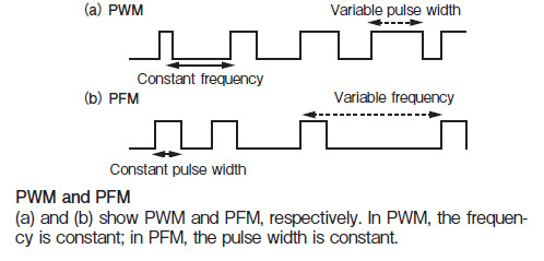
If it can help some people, I've found this image useful to learn the difference between PFM and PWM:

http://i76.servimg.com/u/f76/15/74/35/09/pwm_pf11.jpg

12

Re: Tutorial: How to Write a 1-Bit Music Routine

garvalf: Thanks, that is quite useful. I'll integrate that into the first part of the tutorial.
Shiru, Hikaru: Since Hikaru deleted his posts, I've moved the rest of the "discussion" to OT for the time being. Will delete it in a while if nobody objects.

Re: Tutorial: How to Write a 1-Bit Music Routine

Wow, very impressive write-up. Congratulations, utz!

Re: Tutorial: How to Write a 1-Bit Music Routine

The stitch engine updates all four counters first, and then outputs a single pulse if any of them have expired. I'll have to experiment using a separate pulse for each counter.

15

Re: Tutorial: How to Write a 1-Bit Music Routine

You can actually combine those ideas. Let me explain...

Part 9: More Soundloop Tweaks

In this part, I'll discuss two advanced tricks that you can use to open up new possibilities and further speed up your sound loops. I've learned these tricks from code by introspec and Alone Coder, respectively.


Accumulating Pin Pulses

The first trick applies to the PFM/pin pulse method of synthesis. First, let's take a look again at our PFM engine code from Part 5, and modify it to use 16-bit counters.

BC = base frequency channel 1
IX = freq. counter ch1
DE = base freq. ch2
IY = freq. counter ch2
HL = timer

soundLoop:
       add ix,bc                ;update counter ch1
       sbc a,a                  ;A = #FF if carry, else A = 0
       and #10                  ;A = #10 || A = 0
       out (#fe),a              ;output state ch1
       
       add iy,de                ;same as above, but for ch2
       sbc a,a
       and #10
       out (#fe),a
       
       dec hl                   ;decrement timer
       ld a,h
       or l
       jp z,soundLoop           ;and loop until timer == 0

Now, instead of outputting the pin pulses immediately after the counter updates, we can also "collect" them. This will potentially save some time in the sound loop and will give better sound, because the pin pulses will be longer.

In the following example, register A holds the number of pulses to output, and A' will hold #10.

soundLoop:
       add ix,bc                 ;counter.ch1 := counter.ch1 + basefreq.ch1
       adc a,0                   ;IF carry, increment pulseCounter
       
       add iy,de                 ;counter.ch2 := counter.ch2 + basefreq.ch2
       adc a,0                   ;IF carry, increment pulseCounter

       or a
       jp nz,outputOn     
       out (#fe),a              ;OUTPUT state
       nop\nop\nop              ;adjust timing
       
                                ;now we can't use A to check the counter, hence...       
       dec l                    ;decrement timer lo-byte
       jp z,soundLoop           ;and loop if != 0
                                ;this is faster on average anyway, so use it whenever you can.      
       dec h
       jp z,soundLoop           ;and loop until timer == 0
       
outputOn:
       ex af,af'
       out (#fe),a
       ex af,af
       dec a                    ;decrement pulseCounter
       
       dec l                    ;decrement timer lo-byte
       jp z,soundLoop           ;and loop if != 0
                                ;this is faster on average anyway, so use it whenever you can.      
       dec h
       jp z,soundLoop           ;and loop until timer == 0

Even better, you can use this trick to simulate different volume levels, by adding a number >1 to the pulse counter on carry. Just don't overdo it, because eventually the engine will overload, ie. it will take too long until the engine works through the "backlog" of pulses to output. This method is used in OctodeXL, btw.


Skipping Counter Updates

You have a great idea for a sound core, but just can't get it up to speed? Well, here's a trick you can use to make your loop faster.
This trick is mostly relevant to pulse-interleaving engines with more than 2 channels.

The idea here is that you don't have to update all counters on each iteration of the sound loop. It is however important that you output all the states every time,
and that the volume (read: time taken) of each of the channels is equal across loop iterations.

Here's a theoretical, not very optimized example.


DE  = base frequency ch1
IX  = counter ch1
H   = output state ch1
SP  = base frequency ch2
IY  = counter ch2
L   = output state ch2
B   = timer

       ld hl,0                    ;initialize output states
       ld c,#fe                   ;port value, needed so we can use out (c),r command
       
soundLoop:
                         ;---LOOP ITERATION 1---
       out (c),h         ;12      ;OUTPUT state ch1
                         ;^ch2: 40
       add ix,de         ;15      ;counter.ch1 := counter.ch1 + basefreq.ch1
       out (c),l         ;12
                         ;^ch1: 27
       sbc a,a           ;4       ;IF carry, toggle state ch1
       and #10           ;7
       ld h,a            ;4
       ld a,r            ;9       ;adjust timing
       nop               ;4
 
                         ;---LOOP ITERATION 2--- 
       out (c),h         ;12
                         ;^ch2: 40
       add iy,sp         ;15      ;counter.ch2 := counter.ch2 + basefreq.ch2
       out (c),l         ;12
                         ;^ch1: 27
       sbc a,a           ;4
       and #10           ;7       ;IF carry, toggle state ch2               
       ld l,a            ;4
       djnz soundLoop    ;13      ;decrement timer and loop if !0

16 (edited by Hikaru 2015-09-06 17:10:28)

Re: Tutorial: How to Write a 1-Bit Music Routine

A suggestion for reducing row transition noise in 'pulse interleaved' engines: streamline your data fetcher and throw in a few OUT #FE's in there to keep the beeper afloat so to speak. If the outer loop in your sound generation code uses A', chances are the beeper state is preserved in A so you can try something like EXA: XOR #10: OUT (#FE),A: EXA for a better effect. (I haven't actually tried any of this though!)

Edit: thinking about it, clicks are just as likely to happen (e.g. when approaching 0% and 100%), so probably not worth it

Re: Tutorial: How to Write a 1-Bit Music Routine

utz wrote:

What's important to know is that delay caused by IO contention affects our sound loop timing. Which is bad, as I've explained above. The solution however is rather trivial: You just need to make sure that the number of t-states your sound loop takes is a multiple of 8. That's all there is to it.

Just noticed that this needs a tiny correction. This advice is only correct when the sound loop contains only a single OUT command. In the case when there are several OUT commands, this won't be good enough. What you actually need to ensure is that the timings from any OUT command in your sound loop to any other OUT command in your sound loop is a multiple of 8. This automatically ensures the number of t-states in the sound loop is a multiple of 8, but this is, generally speaking, a stricter requirement.

18

Re: Tutorial: How to Write a 1-Bit Music Routine

Aye, added this to the post. Going by my experiences with 7d7e I'd say this may be considered more as a general guideline for "optimal design", rather than something that needs to be strictly adhered to (like the "stable timing" rule). Nevertheless it's a viable piece of information, so thanks for pointing this out!

I have some plans to extend this tutorial a bit further, but at the moment I lack the time to do so. Think it'll have to wait till next year. Of course everybody else is welcome to add parts, too.

Re: Tutorial: How to Write a 1-Bit Music Routine

utz wrote:

Aye, added this to the post. Going by my experiences with 7d7e I'd say this may be considered more as a general guideline for "optimal design", rather than something that needs to be strictly adhered to (like the "stable timing" rule). Nevertheless it's a viable piece of information, so thanks for pointing this out!

I have some plans to extend this tutorial a bit further, but at the moment I lack the time to do so. Think it'll have to wait till next year. Of course everybody else is welcome to add parts, too.

I think it depends on the type of mixing that you use. The engines with narrow spikes, e.g. Tim Follin engines or Shiru's "Octode" are less sensitive to it, so for them it maybe difficult to even notice the difference. However, for longer duty cycles, e.g. "Savage", the difference is clear and pronounced. Due to relatively low quality of the beeper sound the distortions produced by the contention may be considered insignificant, however, they are easy to hear and are very unmusical, because they result in unstable timing, as well as introduce a 50Hz component into the sound.

I never did everything I hoped to do with the "Savage" due to the lack of time. When I find the time, I will rebuild the classical "Savage" tunes with the new engine, so that everyone can see what's the big deal.

20

Re: Tutorial: How to Write a 1-Bit Music Routine

Yeah, I find that with pin pulse engines, you can usually get away with breaking most, if not all of the "rules".
That aside, please don't get me wrong - I don't doubt that observing this would lead to a major sound improvement. What I mean is that with the kind of >3 channel PuInt and especially wavetable synthesis, it's pretty much impossible to pull off the correct 8t alignments. Which shouldn't deter us from writing those kind of engines wink Nevertheless I'm looking forward to a potential "Savage Ultra" wink

Btw, if you find some time, could you write up something: The theoretical basis for writing a multi-channel routine for 16K Speccy. Been meaning to make one for ages, but I just can't wrap my head around it.

Re: Tutorial: How to Write a 1-Bit Music Routine

OK, got you, will try to do it when I have a bit more time.

Re: Tutorial: How to Write a 1-Bit Music Routine

utz wrote:

What I mean is that with the kind of >3 channel PuInt and especially wavetable synthesis, it's pretty much impossible to pull off the correct 8t alignments.

I was a bit undecided, whether to write about this for a while... You see, I disagree. I think this can always be done. It is not always easy, yes, e.g. "Savage HD" nearly did my head in, very, very messy thing. But it can be done.

23

Re: Tutorial: How to Write a 1-Bit Music Routine

Ok, then we have no choice but to duel it out big_smile big_smile big_smile
I just had a glance at my 7d7 engines, seems it would be possible in more cases than I thought, though I don't see it for all of them, namely not quattropic and xtone (and especially the latter would actually benefit greatly from it). Well, I'll definately give it more thought in the future, though I'm still not totally convinced. As a matter of fact, I've got a new, very fast wavetable player in the works where it definately won't work, as the sound core consists of little more than repeatedly doing out (#fe),a, rrca wink

24 (edited by introspec 2015-12-07 17:56:44)

Re: Tutorial: How to Write a 1-Bit Music Routine

Yeah, that would be way to do it smile
I actually have got several types of PWM coded this year, which are, surprise, surprise, not literally "out (#fe),a : rrca", but ain't far from it. In each case 8 t-state alignment is satisfied. Yes, it can be done. I am pretty much convinced now. The only thing you lose is the possibility to have better than 4-bit resolution for your PWM (e.g. Alone Coder had 5- or 6-bit resolution in his demos, but his demos would not work well on 48K).

I guess my point is, 8t alignment is a pain, but not the worst kind of pain there is out there smile

25 (edited by introspec 2015-12-06 23:52:59)

Re: Tutorial: How to Write a 1-Bit Music Routine

Just as an illustration: this is what quattropic would sound like, when it is aligned to 8t. As we discussed, the effect of alignment can be subtle, but I hope you can hear that the messy distortion is gone now (I do not even know how to describe it).

Update: looked into xtone, hmm, nah, maybe next time! smile