Topic: Tutorial: How to Write a 1-Bit Music Routine
Hiya folks, in this tutorial I'm going explain how you can write your own multi-channel music routines for 1-bit devices. If you have any questions or suggestions, feel free to post in this thead anytime ![]()
There are various 1-bit synthesis methods. I'm going to demonstrate only the two most common ones here. For explanation I'll mostly use my own flavour of pseudo code, and parallel to that I'll give real-life Z80 asm examples, as it would be done on a ZX Spectrum computer.
Index
Part 1: The Basics
Part 2: Adding a Loader/Wrapper
Part 3: Calculating Note Counters
Part 4: 16-Bit Counting
Part 5: Improving the Sound
Part 6: Drums
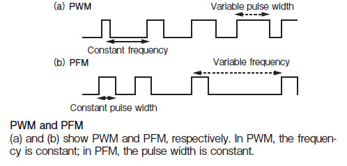
Part 7: Variable Pulse Width
Part 8: Why PFM Engines Have No Bass
Part 9: More Soundloop Tweaks
Part 10: Simple PCM/Wavetable Synthesis
Part 11: Sound Tricks - Noise, Phasing, SID Sound, Earth Shaker, Duty Modulation
Part 12: Synthesizing Basic Waveforms: Rectangle, Triangle, Saw
Part 1: The Basics
Method 1 uses a synthesis procedure called Pulse Frequency Modulation (PFM) at it's heart. Because of the thin, razor-like pulses it produces, PFM is also known as the "pin pulse method". It is used in many engines like Octode, Qchan, Special FX/Fuzz Click, or Huby. The approach allows for mixing of many software channels even on slow hardware, but usually does not reproduce bass frequencies very well.
Ok, let's take a look at how the method works. Assume we have the following variables:
counter1 - a counter which holds the frequency value for channel 1. On Spectrum, let's use register B.
counter2 - a counter which holds the frequency value for channel 2. On Spectrum, let's use register D.
backup1 - a copy of the initial value of counter1. On Spectrum, let's use register C.
backup2 - a copy of the initial value of counter2. On Spectrum, let's use register E.
state - the output state of channel 1, can be off (0) or on (1). On Spectrum, we'll use A.
timer - a counter which holds the note length. Let's use HL for that.
So, in order to synthesize our two software channels, we do the following:
PSEUDOCODE                           ZX SPECTRUM ASM

  DISABLE INTERRUPTS                        di               # running interrupts will throw off timing

soundLoop:                           soundLoop:

  state := off                              xor a
  DECREMENT counter1                        dec b
  IF counter1 == 0 THEN                     jr nz,skip1
    state := on                             ld a,#10
    counter1 := backup1                     ld b,c
  ENDIF                              skip1:
  OUTPUT state1                             out (#fe),a

  state := off                              xor a
  DECREMENT counter2                        dec d
  IF counter2 == 0 THEN                     jr nz,skip2
    state := on                             ld a,#10
    counter2 := backup2                     ld d,e
  ENDIF                              skip2:
  OUTPUT state2                             out (#fe),a

  DECREMENT timer                           dec hl
  IF timer != 0 THEN                        ld a,h \ or l
    GOTO soundLoop                          jr nz,soundLoop
  ELSE
    ENABLE INTERRUPTS                       ei
    EXIT                                    ret
  ENDIF
Method 2 is called Pulse Interleaving, or XOR method. It is used in engines like Tritone, Savage, Wham! The Music Box, and Phaser1. This method will generate a more classic chiptune sound with full square waves and good bass. The drawback of this approach however is that it is more limiting in terms of the number of channels that can be generated.
Assume we have the same variables as in example 1. However, this time we'll use the H register to keep track of state1, and L to keep track of state2. That means we can't use HL as our timer anymore. Well, luckily we have IX at our disposal as well.
In addition, we need a constant which holds a value that will toggle any output state between off and on. We'll call it ch_toggle. On Spectrum, a value of 10h or 18h will do the trick.
PSEUDOCODE                            ZX SPECTRUM ASM

   state1 := off                            ld h,0
   state2 := off                            ld l,0
   DISABLE INTERRUPTS                       di

soundLoop:                           soundLoop:

  DECREMENT counter1                        dec b
                                            ld a,h     ; load state1
  IF counter1 == 0 THEN                     jr nz,skip1
    state1 := state1 XOR ch_toggle          xor #10 \ ld h,a
    counter1 := backup1                     ld b,c
  ENDIF                              skip1:
  OUTPUT state1                             out (#fe),a

  DECREMENT counter2                        dec d
                                            ld a,l     ; load state2
  IF counter2 == 0 THEN                     jr nz,skip2
    state2 := state2 XOR ch_toggle          xor #10 \ ld l,a
    counter2 := backup2                     ld d,e
  ENDIF                              skip2:
  OUTPUT state2                             out (#fe),a

  DECREMENT timer                           dec ix
  IF timer != 0 THEN                        ld a,ixh \ or ixl
    GOTO soundLoop                          jr nz,soundLoop
  ELSE
    ENABLE INTERRUPTS                       ei
    EXIT                                    ret
  ENDIF
A note those willing to try this on ZX Spectrum - beware that the code needs to run from uncontended RAM. Running from contended RAM (ie. any address below 8000h) will completely destroy the routine's timing, producing random screeching noises instead of recognizable tones.
And that's all for part one, if you have any questions feel free to post them here.