Excellent! I find the new block system very intuitive, and it will indeed help to speed up the (already fast) workflow.
Btw, how difficult would it be to display an automatically generated block list to the right of the screen (accessible with some hotkey, for faster navigation in the song)?
801 2016-03-09 08:55:40
Re: 1tracker v0.47 (166 replies, posted in Sinclair)
802 2016-03-08 20:53:01
Re: BuzzKick (1tracker) (9 replies, posted in Sinclair)
Hmm, I don't even understand why this doesn't cause massive cross-detune all the time.
That said, wouldn't it be possible to combine the pins after all, by adding up the delay values of both channels?
Edit: What exactly are the values that get fed into the variable delay? Is the delay for the 0-pulse some kind of inverse of the 1-pulse, ie the longer the 1-pulse delay, the shorter the 0-pulse one?
803 2016-03-08 18:01:44
Re: BuzzKick (1tracker) (9 replies, posted in Sinclair)
Neat, I'm especially surprised you managed to balance the volume between the sampled drums and the tone channels.
I'm still pretty bad at reading other people's code, so I'll need a bit of time to really dig into the code.
Also noticed there are some UI changes... got any plans with that, or is it just changes in SDL?
804 2016-03-08 15:26:40
Re: What hardware equipment I need to make 1bit chiptune? (8 replies, posted in General Discussion)
Yeah, there's the 1-bit AVR synth. Also, the famous 1-bit groovebox has some very crude means of syncing to a midi clock. There might be others as well.
805 2016-03-07 11:36:27
Re: 7 days, 7 (new) beeper engines (65 replies, posted in Sinclair)
Tadaa, here we are again with our popular series "Fixing the quattropic converter". In this episode, expert C++ coder utz will try a completely rewritten, all-new algorithm for determining the play mode! Be sure to have a good laugh at the latest bugs!
Download is still here: https://github.com/utz82/ZX-Spectrum-1- … p?raw=true
806 2016-03-06 18:29:37
Re: What hardware equipment I need to make 1bit chiptune? (8 replies, posted in General Discussion)
Hey gensek, welcome aboard! Yes, as garvalf said, you actually only need a Speccy (and perhaps a mixer/amp so you can boost the signal a bit when loading wav files created from .taps). However, tape/wav loading is slow and tends to fail frequently when doing it in loud environments, so if you plan on doing more work with 1-bit and/or playing this stuff for live shows, you might want to get a divIDE or divMMC for faster, more reliable loading. (The page I linked to is the original manufacturer, but there are other sellers/manufacturers as well, just google it).
807 2016-03-06 18:21:26
Re: next gen engine ideas (135 replies, posted in Sinclair)
Very interesting and pleasant sound! Wavetables are nice and good, but this is something that's uniquely 1-bit/beeper sounding while at the same time moving forward in terms of technique. Would definately use an engine with this.
808 2016-03-04 15:44:10
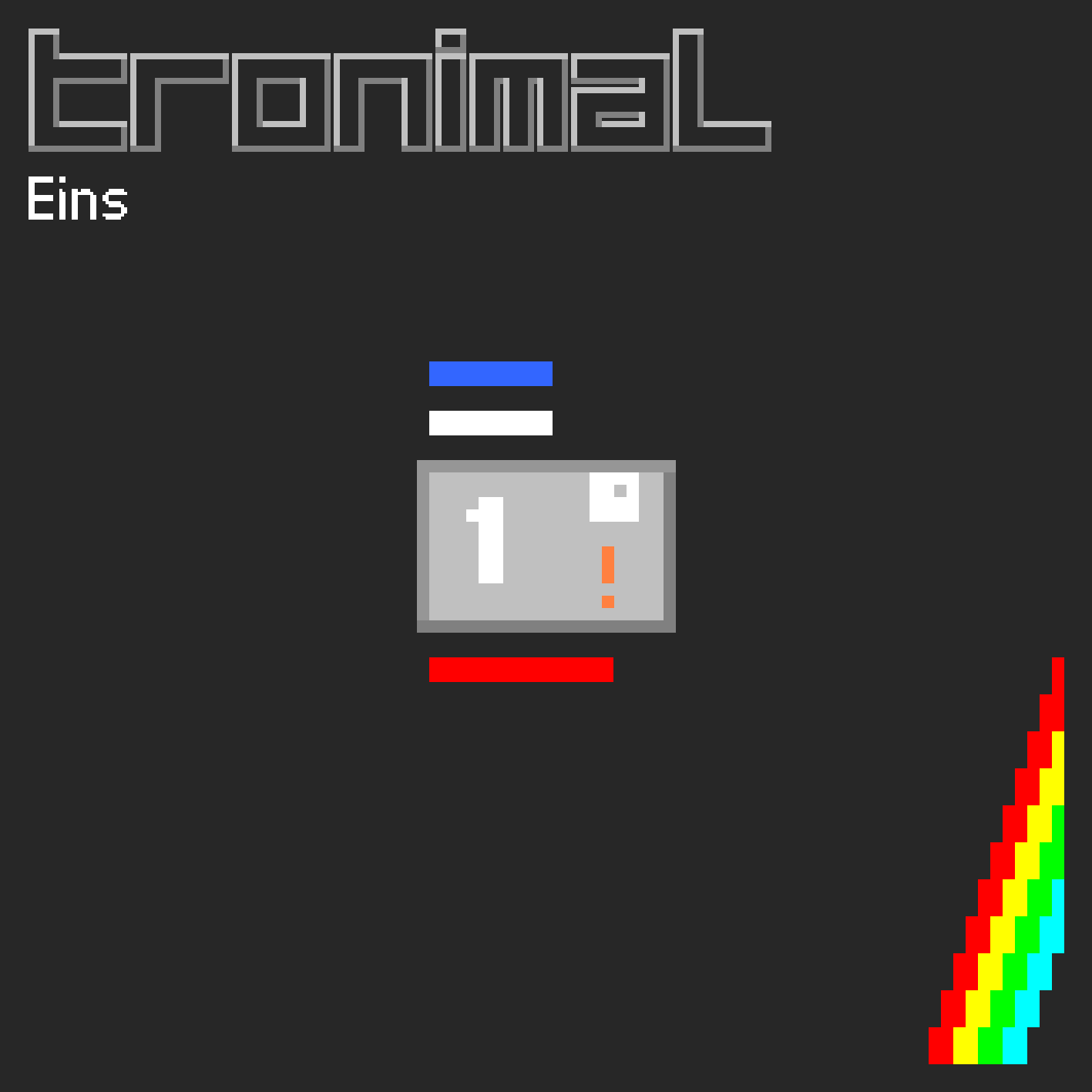
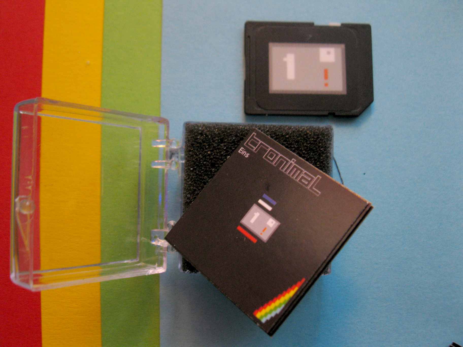
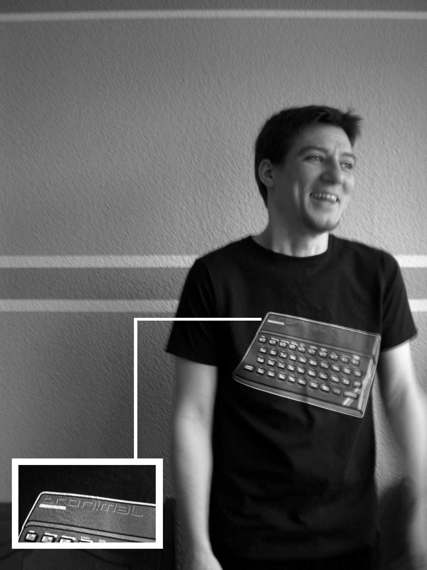
Topic: New Album: Tronimal - Eins (2 replies, posted in Sinclair)
This guy has a unique take on 1-bit music. Check it out.
Tronimal wrote:
HELLO WORLD!
The new ZX Spectrum Beeper Album
"Tronimal - Eins"
is available now!
As Stream, Download or limited SD Card Version.
Visit http://tronimal.bandcamp.com/
This Album is completely written for
Sinclair ZX Spectrum 48K Beeper
using different engines in Beepola.
Music and lyrics written by Tronimal,
except Durchbruch (original song by Zweitgolf).
All songs were recorded from a real Sinclair ZX Spectrum 48K
without any extension or modification.Stream/Download Version contains 7 songs. Available for free as usual, with pay-what-you-want option.
Playtime 11:47 MinThe Special SD Cart Edition is limited to a maximum of 100 pieces.
It contains 8 songs, as well as 8 TAP files to play the instrumental versions on original ZX Spectrum or via emulator.
Playtime 13:00 Min
There will be a CD released later as well. It contains 10 songs. The releasedate is unknown yet.
Playtime 16:14 MinT-Shirts are in the making and one of them is already on the way.
Much better Quality than my Shirts before.
Colour Black
///
additional information:
SD Card Version contains:
SD Card with Label-Sticker, an extra Sticker, a Booklet (3x3cm) and a transparent Shell!///
Many Thanks to Thomas, Jens, Markus, irrlicht project & Zweitgolf!
///
CC-BY 2016
For more information visit www.tronimal.de
809 2016-03-04 00:26:54
Re: 7 days, 7 (new) beeper engines (65 replies, posted in Sinclair)
sigh it's a curse with this engine, or rather with the converter. In theory the demo tune should be unchanged, so it's probably the converter causing the trouble. I'll look into it. Thanks for reporting, in any case.
810 2016-03-04 00:23:12
Re: new engine: fluidcore (4 replies, posted in Sinclair)
Thanks guys ![]()
Just checked it on +2A myself... looks funky indeed ![]() Ideally it should look more like this on 48K, too - then sound would be cleaner. I've got some ideas to improve sound by always keeping the beeper afloat rather than shutting it off at volume 0. But it'll be quite some work to implement, and I'll have to reduce the mixing rate, though there's some room for that.
Ideally it should look more like this on 48K, too - then sound would be cleaner. I've got some ideas to improve sound by always keeping the beeper afloat rather than shutting it off at volume 0. But it'll be quite some work to implement, and I'll have to reduce the mixing rate, though there's some room for that.
811 2016-03-03 15:35:18
Topic: new engine: fluidcore (4 replies, posted in Sinclair)
What, another one? hehehe
fluidcore is a 4 channel PCM wavetable player for the ZX Spectrum beeper, using looped 256 byte waveforms. It offers a total of 17 volume levels, and can handle up to ~860% overdrive when the maximum volume level is exceeded. Sound is mixed at approximately 23 KHz.
Needless to say, I'm pretty proud of this thing ![]() Also, the good news is that I've managed to make an XM converter for it. So, hope you'll enjoy!
Also, the good news is that I've managed to make an XM converter for it. So, hope you'll enjoy!
download (includes XM converter, pasmo is required)
source code
demo video
48K hardware recording
812 2016-03-01 11:11:57
Re: 1-bit music on Thomson 8-bit computers (3 replies, posted in Other Platforms)
Ah, nice! Must've been quite a challenge to get it up to speed on 6809. I'm curious if the guys will present something at Forever. I think I might've actually met them back at Forever 2010 (where LCD taught me my first steps of Spectrum coding ;D)
813 2016-02-23 21:00:48
Re: HoustonTracker 2 (TI-82/83/83+/84+) (130 replies, posted in Calculators & Pocket Computers)
Thanks guys! Btw I made quick video detailing some of the new features, check it out:
https://www.youtube.com/watch?v=tKfni5-_42g
814 2016-02-19 14:29:49
Re: HoustonTracker 2 (TI-82/83/83+/84+) (130 replies, posted in Calculators & Pocket Computers)
Good news everyone, HoustonTracker 2.1 has been released! Several new effects, improved keyhandling, and of course various bugfixes were implemented. For full details, check the original post in this thread.
815 2016-02-16 23:17:26
Re: new engine: wtfx (5 replies, posted in Sinclair)
Regarding a potential new tracker, I just remembered an old idea I had when 1tracker came out.
The main disadvantage of the pattern-less approach in 1tracker is that with increasing song length, moving around in the song, keeping track of what is what, and changing large portions of the sequence becomes tedious and demands a lot of attention. So, how to solve this?
My idea is to have an additional visual representation of the sequence - not unlike the Beepola pattern sequence in terms of layout, but translated to the marker concept in 1tracker. Each section (ie. block of song data defined by two markers) will be numbered, and shows up as a block in the sequence layout. This is fluid, ie. when a marker is removed, the sequence view changes accordingly (numbering should stay to avoid confusion). Perhaps there should also be the possibility to name sections, or assign a color to them, for those structures the user decides to keep permanently.
Now, obviously this wouldn't quite work like a traditional pattern matrix, ie. blocks can't be used multiple times. But it would still offer several possibilities to the user:
- clicking on a block will move you to the according position in the song data.
- drag blocks to move them around in the sequence. Multiple consecutive blocks can be selected with Shift+Click.
- Clone one or several consecutive blocks by marking source blocks with Ctrl-Click, then right-click at the desired position to insert the clone.
- Cut sections by marking them like above, then Del. Freed up section numbers may be re-used by the auto-numbering.
Well, just some random ideas here. I have neither the time nor the skills to actually program something like this.
816 2016-02-14 00:59:24
Re: 7 days, 7 (new) beeper engines (65 replies, posted in Sinclair)
Upgraded the compile scripts for the quattropic package. They will now generate the BASIC loader at compile time, adding a simple title screen and enabeling automatic assembly at an arbitrary address. There are two ways to use the new features - either via the new "interactive-compile" scripts, or by adding some parameters when running the regular compile scripts. Details for the latter can be found in the readme.
Thanks to Tufty for testing my Win build of zmakebas, which is now included in the package.
817 2016-02-13 20:31:58
Re: HoustonTracker 2 (TI-82/83/83+/84+) (130 replies, posted in Calculators & Pocket Computers)
Damn, what an ordeal! Does this also happen if you try to transfer via command line ("tilp ti82 Silverlink ht2.82p")?
818 2016-02-12 22:38:11
Re: Commodore 128 (2 replies, posted in General Discussion)
Hehe, I actually got a 128D sitting on my desk ![]() Was wondering about the Z80, too. But all the C= coders I've talked to so far have told me that it's not worth it because the Z80's power is seriously limited by the system. So, in order to make some 1-bit music on the machine, one would be better off coding for the 8502. I don't really like 65xx asm though, so... not for me
Was wondering about the Z80, too. But all the C= coders I've talked to so far have told me that it's not worth it because the Z80's power is seriously limited by the system. So, in order to make some 1-bit music on the machine, one would be better off coding for the 8502. I don't really like 65xx asm though, so... not for me ![]()
Btw check this out: http://csdb.dk/release/?id=94238 ![]()
819 2016-02-12 13:53:53
Re: HoustonTracker 2 (TI-82/83/83+/84+) (130 replies, posted in Calculators & Pocket Computers)
Thx. Sent you a mail.
820 2016-02-10 20:21:32
Re: Best beeper music: top100 rating. (15 replies, posted in General Discussion)
Abrimaal's collection (= AYGOR) has already been added, I think. And yes, moroz needs .ay. I have some cruddy (Linux) toolchain which helps with the conversion, but it's still a lot of manual work.
821 2016-02-08 18:40:53
Re: Best beeper music: top100 rating. (15 replies, posted in General Discussion)
Neat! But yeah, definately needs more votes. Also yes, I think e.g. a lot of stuff from BotB is still missing. Unfortunately I don't have enough time to sift through and convert those entries atm. I think it would be really helpful if there was a conversion tool which would make the process a bit less time-consuming. Perhaps you could get in touch with puke7 from BotB to see if it's possible to utilize meta-data from BotB somehow?
In any case, I've added a link in the forum header, hope that'll help to generate a few clicks ![]()
822 2016-02-08 18:23:47
Re: List of 1-bit routines and editors for Sinclair ZX machines (7 replies, posted in Sinclair)
Thanks for the info! I have to admit the whole thing is a bit of a mystery to me - was the engine actually ever released in source format?
823 2016-02-07 18:21:40
Re: 1-Bit Forum Compo: Results (10 replies, posted in General Discussion)
Yeah, the usual problems... hope the site will be back up in a few days.
824 2016-02-07 16:04:03
Re: HoustonTracker 2 (TI-82/83/83+/84+) (130 replies, posted in Calculators & Pocket Computers)
Ok, sorry to hear that. Could you let me know which Windows version you're using though? I'm trying to sort things out with the TiLP developer atm.
825 2016-02-07 00:13:31
Re: HoustonTracker 2 (TI-82/83/83+/84+) (130 replies, posted in Calculators & Pocket Computers)
I'm afraid no. Could you post the console output with the ticalcs error? I'll try to pester the TiLP developer if I can't spot anything obvious.
Another option: Try the latest TiLP beta, perhaps there were some relevant bugfixes. See here: https://www.cemetech.net/forum/viewtopi … 917#244917