301

(5 replies, posted in Sinclair)

A new simple engine is made and added to 1tracker. Nothing too special, but it mixes a few features of various engines: the Earth Shaker engine sounding one (but implemented in a different way), two-channel Tritone-like engine, and sampled drums. This provides a major variety in the loudness, so it may get more dynamics to the 1-bit music.

The engine has two separate tone generation loops, either of those can be invoked for every row, both sharing the same register set to store accumulators and adders, as well as same timings (120t for sound loop, ~30 Khz sample rate). Technically even more different types of engines can be combined like that.

302

(166 replies, posted in Sinclair)

A new engine added without changing the version, Ear Shaver.

if you want to do an authentic sound of a LCD game, you should also consider memory constrains. The early games didn't have much of jingles and complex sound effects just because the mask ROM size is so limited on SM-510 or TMS1x00. It is just 1024 to 4096 bytes for everything, and it seems the code is quite sparse on those 4-bit MCUs - I mean, it needs more operations to do things because of limitations of the architecture.

Later LCD games, however, had quite a lot of music pieces, sometimes polyphonic, with white noise, or even actual (not LPC encoded) voice samples - for example, some of Brick Game versions. Those might be using some kind of 6502 core, but it is not known for sure.

So I guess you need to pick a period of LCD gaming, and if you want to stick to early ones, keep everything at minimum, if you going for later ones, add more stuff.

I would keep the overall pitch a little bit higher, it will sound better. That's due the way 8253 works, it does not restart count right away once a new divider is loaded, so if your pitch gets very low, like in a kick drum slide, to a few dozen hz, then you need a high pitched sound, it won't start until one period of the low pitched sound gets completed. So if the pitch was at, say, 24 Hz, it may take up to 1/24 second before higher pitch will take effect, but that maybe a time to play another pitch (arpeggiated) already, and it will sound distorted and kind of like having weird gaps or drop outs.

If you always keep pitch weil above the 'frame rate', it will sound good. I.e. if you use 60 hz update rate, try to keep your pitch not lower than 60 Hz, better to keep it higher than 60 Hz most of the time.

Arpeggios is not a problem for piezo speaker itself. Frequency response is, it cuts most of the low and mid-low end (like up to 700 Hz), and has various resonances in the higher end. Take a look:

https://a.pololu-files.com/picture/0J1721.1200.jpg?515c0c5df075fcd84c23e5d32ea31807

Remembered a fun fact, by the way - there is some quite extensive docs on the instruction set of SM-510 and its internals in Russian. It has been published in an IT mag back in 1987, because the Game & Watch has been cloned back then, complete with the MCU and mask ROM containing the Game & Watch program and Nintendo word in an unused area of the ROM.

As an alternative for Monotone, you can use my PCSPE VST plugin. It allows to create very complicated single channel music for actual PC Speaker, and you can use it with your favorite DAW. You can use some of my impulse responses to make it sound like a piezo as well.

Tamagotchi said to have a 6502 core inside. Bandai's LCD game is probably something along the lines of TMS1000.

It is sure possible to make some music routine for SM-510 that would sound more interesting than simple beeps. However, nothing has been done in this area yet, because this isn't some popular thing, it was reverse engineered and emulated just recently, and there is simply no development infrastructure yet. Like, you need an instruction set doc, an assembler, an emulator that allows to test your code, and you likely won't be able to run it on the original HW, as it uses mask ROM.

Another crazy idea to expand the world of 1-bit music.

There is a thing among electronics engineering enthusiasts - homebrew CPUs, usually made of separate TTL 74xx chips. Magic-1 is probably the most famous of them, but there are dozens more. Usually those are self-contained systems, made of dozens of chips, with a little bit of ROM and RAM, some of them has some LEDs, and sometimes a speaker output. Complete with unique instruction sets. Perfect place to apply our skills.

Many of those has way too many parts and no PCB, and of course no emulators available, so it is diffucult to obtain and/or get started. Thus I thought to find one simple design with least amount of chips and a PCB available. MP-4 would be a good choice, exactly a dozen of chips, but it has no PCB (yet), and no well settled down design actually. So after some search I found another one.

That's Nibbler, a 4-bit TTL CPU. It only has 17 chips, runs at 2.46 MHz (~1 MIPS), includes ROM, SRAM, has 16x2 text LCD interface, buttons, and a speaker - our beloved 1-bit one. As the chip count is so low, it can be build on a breadboard/perfboard. There is also a PCB design that used to be sold, it is out of stock, but the files are still there, so it can be reproduced. Even better, it already played some music 5 years ago.

Of course being such a simple 4-bit CPU, it lacks tons of basic features (many of those homebrew designs do), such as stack, or indirect indexing even. But that's just makes it more fun.


For now I have tons of other things to do, but I would like to try this idea out sometime in the future. In meanwhile we can discuss which of existing designs is more accessible and/or interesting, and eventually make the HW available and its emulator made.

308

(35 replies, posted in Other Platforms)

Hardware review #6

With another $8 I finally got my hands on an early AON with the 'large' board that has been designed to fit into the VEF-TA-12 phone case. Although this was the most common design for first half of 1990s due to the relative availability of the phones of this model, mine is made sometime mid 1994 - the phone itself was produced May 1994, latest dates on the chips is May/June 1994, so it is one of the latest of this classic kind. It also has mods on the board made to run Rus 17c firmware (few wires to enable 64K ROM banking, some minor fixes). Surprisingly it is in the most mint condition among all units I got so far. Actually came complete with box and original phone's manual, although the box wasn't in good condition and get damaged further during delivery, so had to get rid of it.

This early large board does all the same like the small one that you seen in these reviews, just with specifics of the analog part of original VEF phone considered, or lack of it - this design replicates analog part of the VEF phone on the board, while the small board omits most of it. The most obvious difference is that huge transformer that got omited later.


Exterior view. The display is placed where the orignal VEF label has been located very conviniently, so it looks just like it was originally designed to be this way.
http://shiru.untergrund.net/temp1/aon_6_1.jpg


Closer look on the display. As you could see on the exterior view, one of digits is noticeably dimmer than others. That's not due to the dynamic refresh, it is clearly visible with naked eye. The same happened with another unit, but another digit is dim. Normally the brightness should be all even. I think this is LED display degradation that happened by some reason. Maybe this unit once froze and remained so for a long time, so dynamic refresh stopped at this digit and worn it out.
http://shiru.untergrund.net/temp1/aon_6_2.jpg


The board. The two extra wires are changes and fixes to support later Rus firmware. One of ROM pins connected to a 8255 output, providing 64K ROM banking support. RD line of the 8253 connected to RD line of Z80, allowing to read back timer registers.
http://shiru.untergrund.net/temp1/aon_6_3.jpg


Close up on the transformer and the extra ROM address line wiring. Interestingly, you can see two logic chips with proper 74xx marking. The ceramics packed EL7493J is in fact a Soviet produced chip made to be exported to other countries. 74LS04, however, seems to be an imported chip.
http://shiru.untergrund.net/temp1/aon_6_4.jpg


Back side of the board. Has hard mounted LED display and buttons of the original phone. Despite the serious looks, these buttons isn't working well, producing many missed or repeated presses, and that's not because they're old now, they always were like that.
http://shiru.untergrund.net/temp1/aon_6_5.jpg

309

(35 replies, posted in Other Platforms)

Thanks a lot for pointing this one out, didn't see it. One issue, though, is that it is GPL, and if I simply use this or MAME implementation, which is the easy way, it'll put the whole project under GPL, which I kind of dislike - I'd rather released it under PD/CC0/WTFPL. That's why I'm trying to cook up my own implementation that is not derived from MAME. Actually I'm trying to fix up my very old implementation from 2007 or so to current needs.

310

(35 replies, posted in Other Platforms)

I'm thinking about an unique one to benefit from the strenghts of the platform, although porting something first to test the grounds is likely. Almost anything can be ported, if it does not take up much RAM (like ZX-7 and ZX-16) - there is plenty of ROM to hold a ton of song data, and CPU speed is a bit faster.

Actually, as I still have troubles with 8253 emulation and other things take priority at the moment, porting an engine or a few is a good next step.

311

(35 replies, posted in Other Platforms)

That's 4046807 (one digit is a bit dim), a phone number of author of the test.

312

(35 replies, posted in Other Platforms)

Modding and testing the hardware

Finally got a ZIF 28-pin socket ($3.4, with quick delivery) and ten Winbond W27C512 DIP28 Flash ROMs ($6.2) from China. The latter is just in case, of course I don't really need that many. Anyways, it now become possible to finish my modifications to the AON unit I'm going to use to occasionally test my software during developing, as well as finishing the emulator - this means relatively frequent tests, and modifications were made to make this process more comfortable. Let's see what has been done. Please note that most of the modifications is only needed to develop software more conviently. You don't really need most of them in order to just use it once its done.

First, I fixed everything inside the case, using tons of hot glue - just like it has been done in 90s.

I added socket for phone handset, to make it detachable. Also added phone line and power source sockets. The power source is now USB Type B, this allows to use any USB phone charger supply, which is really handy, or a power bank - so it is a portable now. As much portable as a regular brick. There is Reset button added that is normally not presented, but useful to do tests.

As I need relatively frequent tests, I decided to use ZIF socket, because normal ROM socket wouldn't provide reliable contact, relatively difficult to connect/disconenct, and would wear out soon. The length of ZIF socket pins and other parts on the board not allowed it to fit into ROM socket directly, so I used yet another ROM socket in between, plugged them into each other like a tower. Not really physically reliable, but it works if used carefully.

I did a hole in the bottom of the phone body to expose ZIF socket for easy Flash ROM replacement. It is a bit too tall, not allowing the phone to stand on a flat surface as it normally should. Thus I added front legs extender, that raises the front part of the body, adding missing height. Not pretty, but does the trick.

I flashed the PHON-LP2 test ROM I mentioned above using WizardProg-87 - all smooth and easy, no issues. A very handy inexpensive piece of Chinese gear, if you happen to burn ROMs time to time. As it is a 512K Flash, but AON only supports 32K, and the test itself is just 2K, I simply copied these 2K all across the 512K image using a HEX editor, to avoid cutting/grounding chip legs (extra address lines). The test worked just fine. I learned how it behaves on this particular board (no 8253 RD, no configuration diodes), and that it plays clicks and short music phrases during testing - good to know in order to make emulator work correctly.

Here is a video of the unit running the test: https://youtu.be/rR_g8js13oY


Flashing the test ROM with the WizardProg-87 burner.
http://shiru.untergrund.net/temp1/aon_mod_1.jpg


Inside of the test unit. Now with extra two sticks of hot glue.
http://shiru.untergrund.net/temp1/aon_mod_2.jpg


Close up of the ZIF socket. It just plugged into a regular socket then into the board, not physically fixed (yet).
http://shiru.untergrund.net/temp1/aon_mod_3.jpg


Newly added reset button on the left, USB Type B socket for the power and phone line socket (just in case I need it for something) on the right.
http://shiru.untergrund.net/temp1/aon_mod_4.jpg


Phone body with bottom part screwed into its place. Extended legs at the front.
http://shiru.untergrund.net/temp1/aon_mod_5.jpg


With a Xiaomi power bank now it makes a fully portable Z80 micro computer.
http://shiru.untergrund.net/temp1/aon_mod_6.jpg

Another small update. Multi mode added - you can use a few fixed pitch instruments on the same MIDI channel using different notes, which is useful for drums. Minor fixes as well.

314

(35 replies, posted in Other Platforms)

Hardware review #5

While I'm struggling with proper 8253 emulation, yet another item of curiosity I got for $7. This is one of the latest AONs built on the custom 8051-based R100-XP MCU, one with on-die AY-3-8910 clone.

As it is one of the latest devices of the era, made circa 2003, build quality is relatively high, and overall it looks more like a properly made consumer product rather than a half-DIY half enthusiast thing. The phone case and buttons has labels in Russian, there is a good packaging box, and a very detailed manual, all in russian too. The board inside called Venus 5, latest of that family. Besides the R100-XP there is not much parts on the board - LED driver, 24LC16 Flash, the main 512K ROM, and a bunch of amplifiers.

The ROM is in fact Flash (EN29LV040 in my unit), mounted into a socket, so it can be modded very easily - if you happen to have a ROM burner with 32-pin PLCC adapter around.

My unit has Rus-28 Sonata firmware, instead of the AY music it features 'MIDI polyphony', as it called in an official schematics book. But there is no dedicated MIDI synth chip on the board, and schematics is barely different from the AY revision (just a few resistors and capacitors). The offical docs from the maker of the Venus boards mention that since build 5713 of the firmware it has a 6-channel MIDI Wavetable Synthesiser, so it seems to be a software synth. As the AY clone is part of the custom MCU, it should be easily usable no matter what board and firmware it is, but the MIDI synth has to be somehow hacked out of the original firmware if someone would like to have it.

The MCU also has a 8-bit DAC, so the firmware features relatively smooth volume control for all sounds.


The packaging box and manual.
http://shiru.untergrund.net/temp1/aon_5_1.jpg


External view.
http://shiru.untergrund.net/temp1/aon_5_2.jpg


Keyboard close-up. The russian labels done in the cheapest way, but at least you can now have idea what the extra buttons doing, plus there is marks on the case itself for the calculator layout.
http://shiru.untergrund.net/temp1/aon_5_3.jpg


Internal view. not much is in there. Unlike all other phones in these reviews, all boards now custom made, and the battery backup pack wires is actually connected to the board.
http://shiru.untergrund.net/temp1/aon_5_4.jpg


Back side of the PCB. 512K Flash ROM is on the left.
http://shiru.untergrund.net/temp1/aon_5_5.jpg


Front side of the PCB. The R100-XP MCU is on the right. Sorry, the mark is so weak there I couldn't catch it to be visible on camera.
http://shiru.untergrund.net/temp1/aon_5_6.jpg

315

(166 replies, posted in Sinclair)

Thanks, will add these changes.

To me there is no such issue with frequent 'no data' error, at least as far as I tested all newly added engines in a few months. One or two engines had this issue, but it happened very ocassionally, but wasn't able to figure it out yet - thought it is engine related, and it is not repeats too often, so I thought maybe other fixes changed that too. Situation was partially similar - by editing the first row, with almost blank tune. Alright, will keep the eye on it.

Logging format has been changed a little bit, more formats added, and whole exporting thing is impoved in general. For one, you can export specified part of the song, or the whole song, without need to cut out the silence inbeginning and end, by marking beginning and end of exporting area with any change for controllers 20 (begin) and 21 (end).

317

(166 replies, posted in Sinclair)

Added more engines without changing the front end version. Mostly old classic engines. Music Box (Wham) - unlike Beepola it is complete with drums, Music Synth 48K, QChan, Tritone, and its new flavour called Tritone Digi (with sampled drums). Also a very basic YM2413 engine LLBasic, in case you're interested in other formats.

318

(35 replies, posted in Other Platforms)

Test ROMs

Since beginning of this thread, I was slowly working on the emulator that was abandoned since 2014. It is a must to develop new firmware efficiently, also a great help to figure out details about the architecture that remain unclear due to mistakes and difference in various schematics available, such as memory and I/O maps, keypad matrix layout, and so on. Now, when it starts to taking shape (more on it later), there is something different than the flood of HW reviews to share.


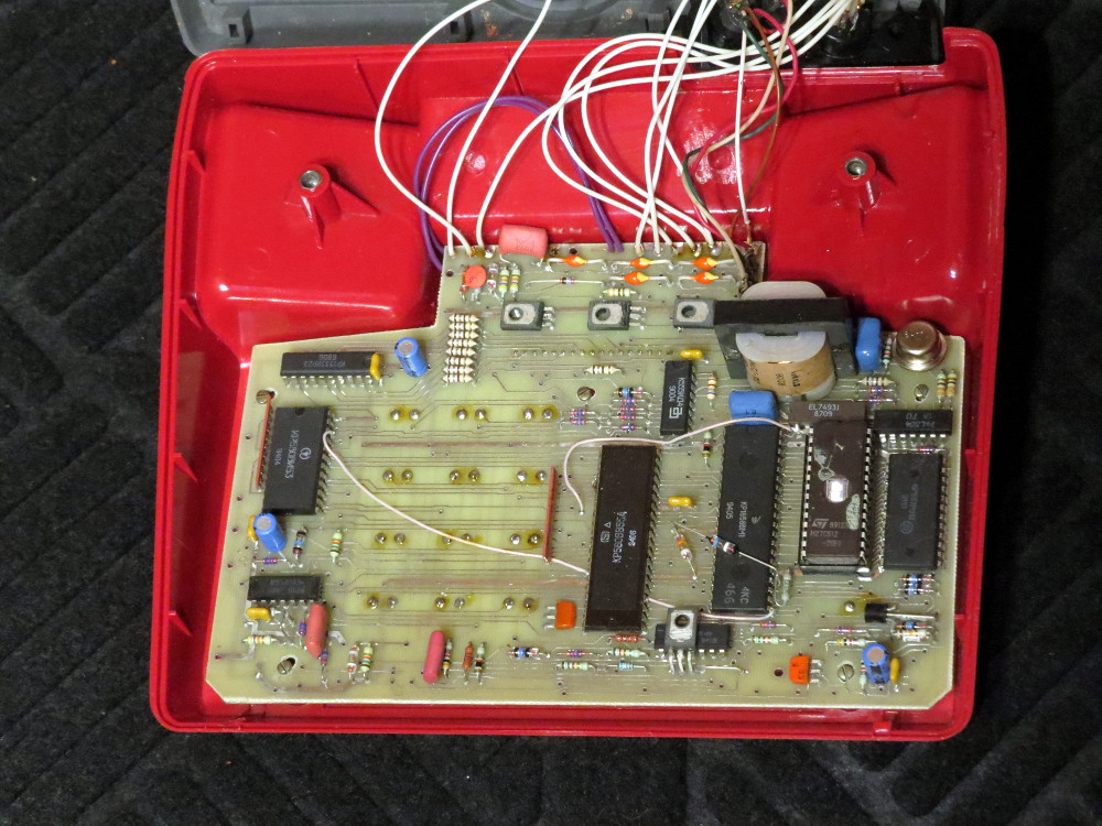
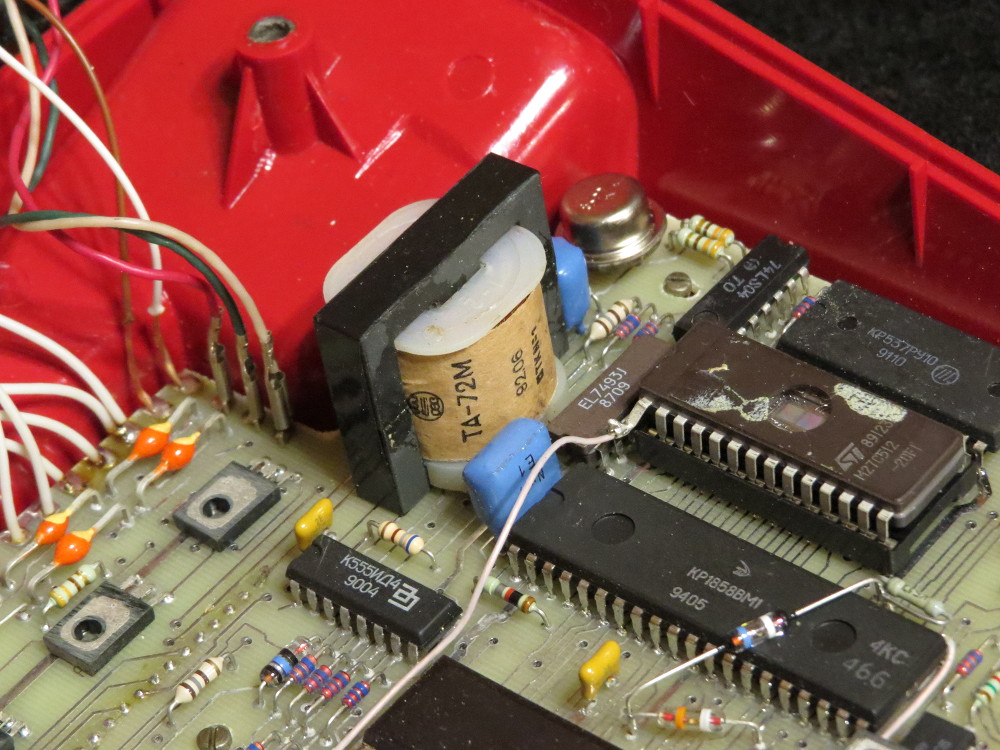
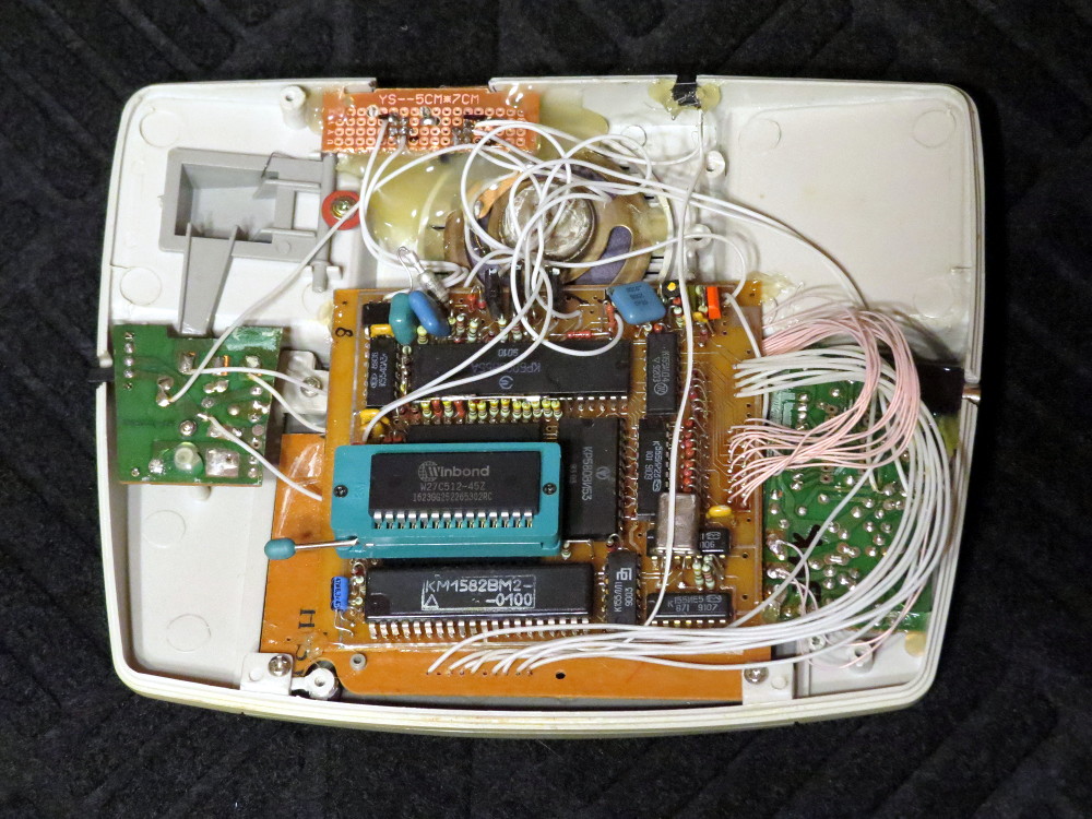
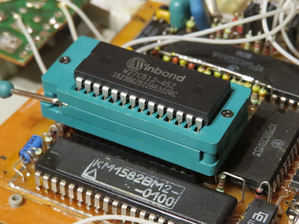
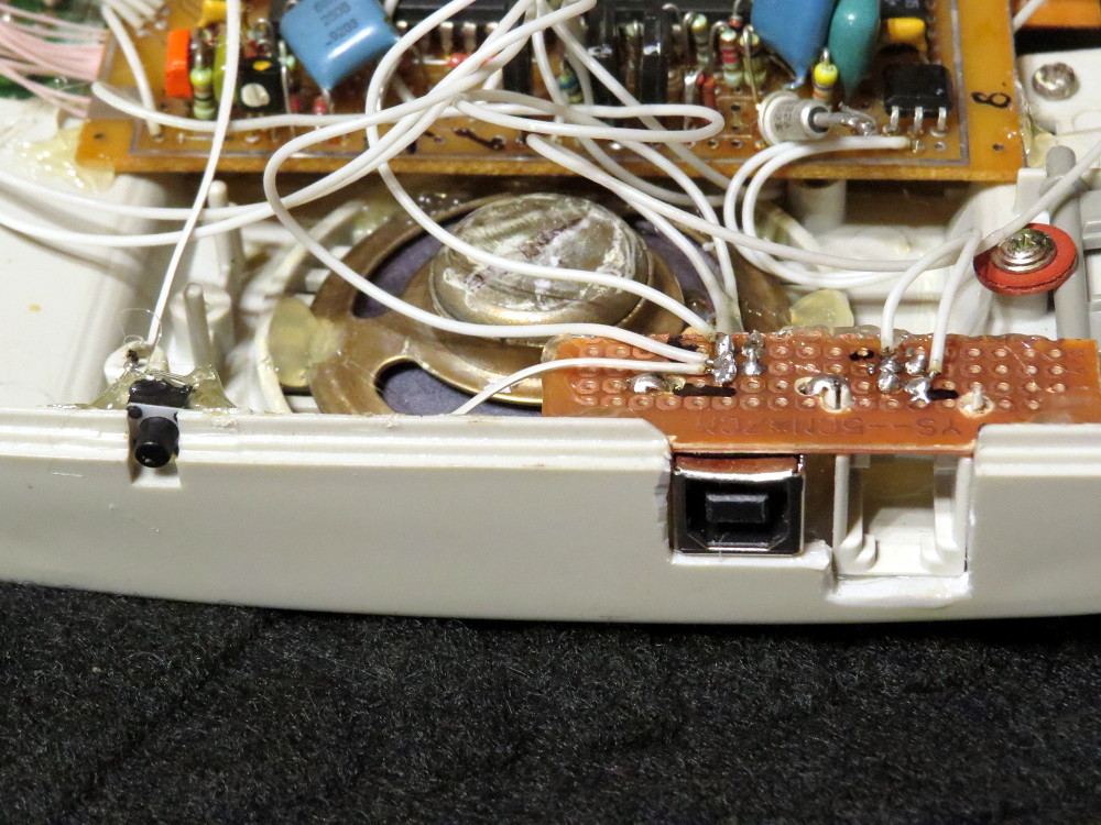
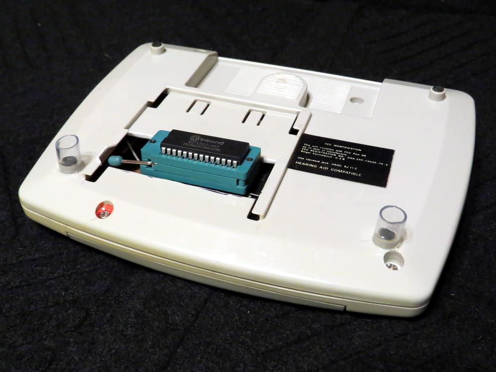
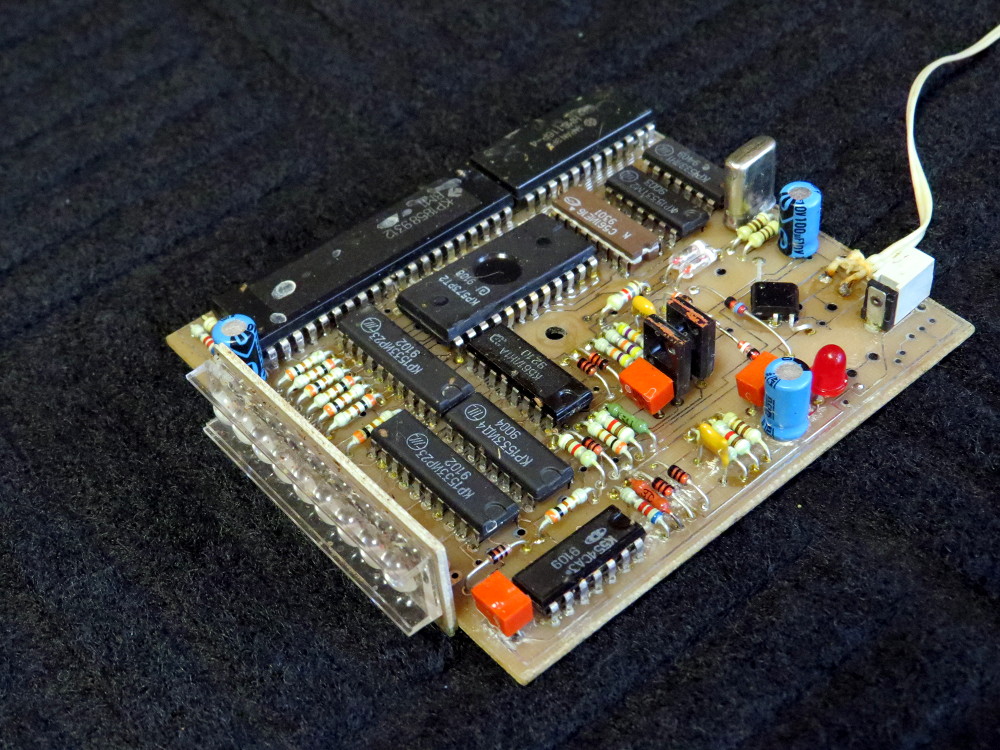
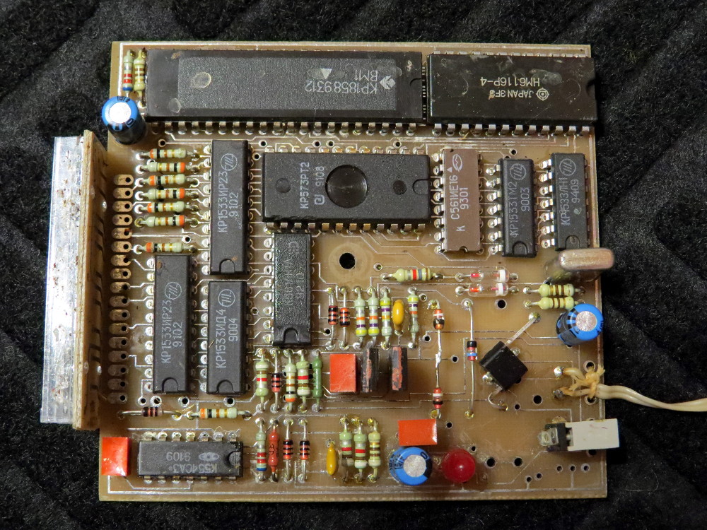
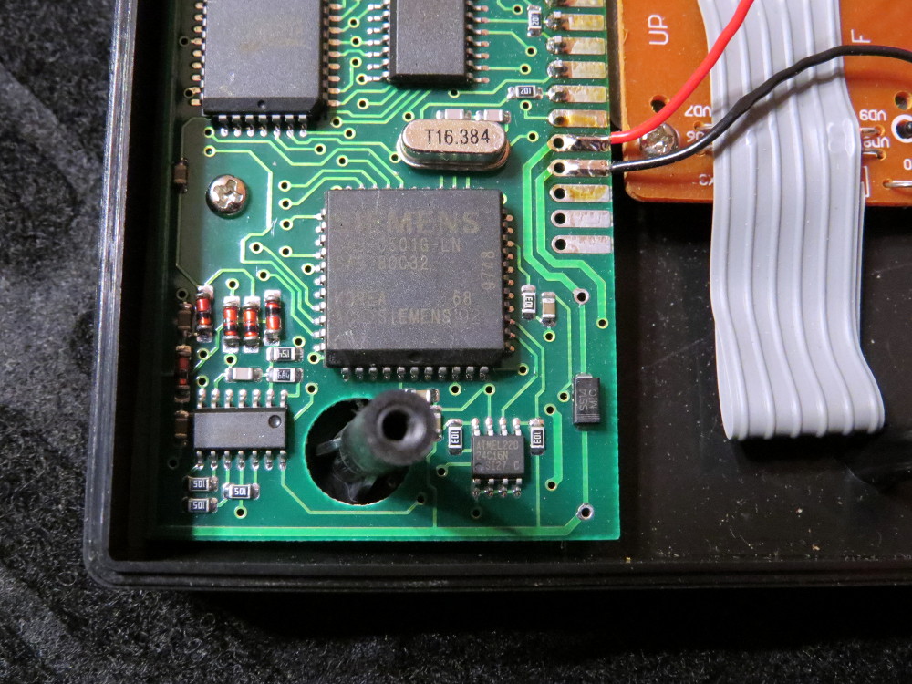
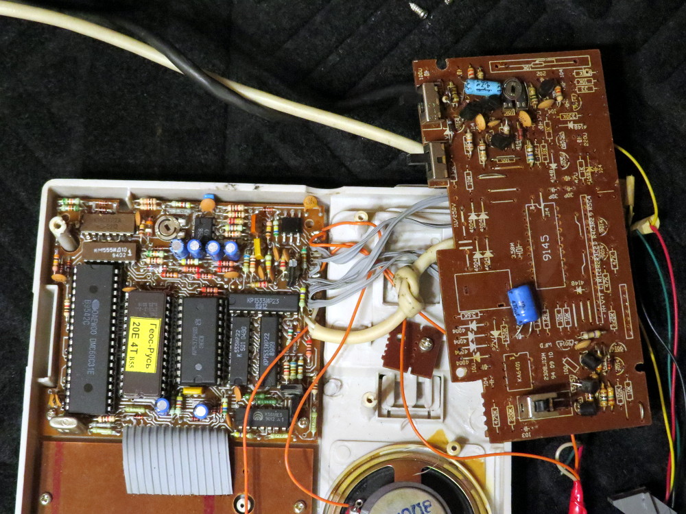
Due to the nature of the platform that was almost like DIY in early years, and due to the way parts were sold in 90s, Z80 boards nearly always has a ROM socket installed (sometimes CPU and other large chips too). As neither parts nor boards were of a great quality, it often was tricky to make the thing work once you assembled it. Thus there was a number of test ROMs from different authors that can test the hardware all the way through, helping you to figure out lots of potential issues ranging from faulty chips to missing connections or short circuits easily. It is a great help in making emulator too, in fact it was a huge help to me. There is normally no such a luxury with emulator development for other platforms, even popular ones.


Test I'm using the most called PHON-LP2.ROM, from 1995. It is one of latest and most complete, judging by the very detailed doc provided with it. It is just 2K, so you can save the 8K ROM banking headache for later. The doc is of course in Russian, so I give just a brief outline of its functionality.

In order to run it requires bare minimum of properly working hardware in order to start, namely no short circuits in CPU address, data, and control lines, correct clock - in other words, functioning CPU.

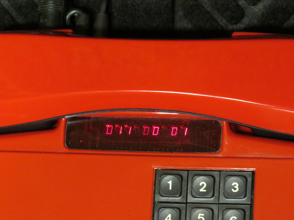
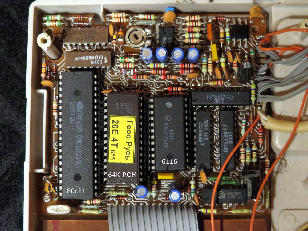
First it tries to check 8255. If there is some problem with it or related parts (listed in the doc), it shows error message using single digit of the display, as multiplexed display is not possible without these parts working correctly.

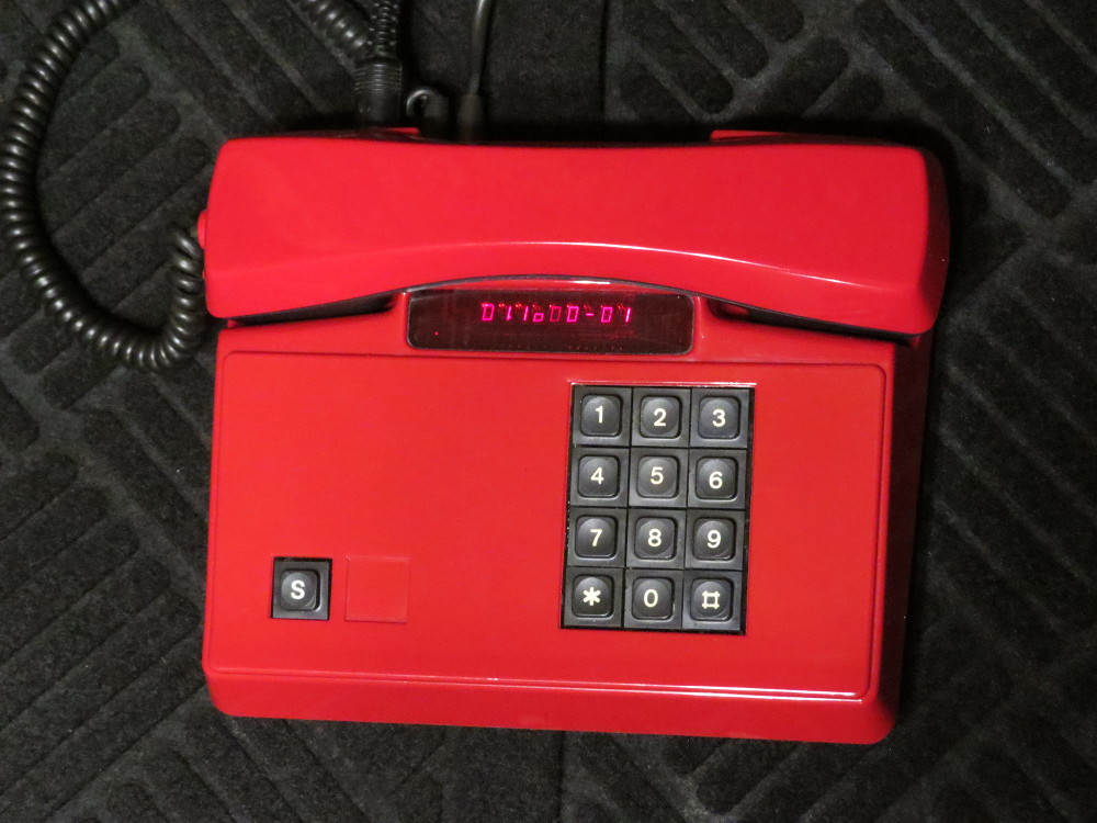
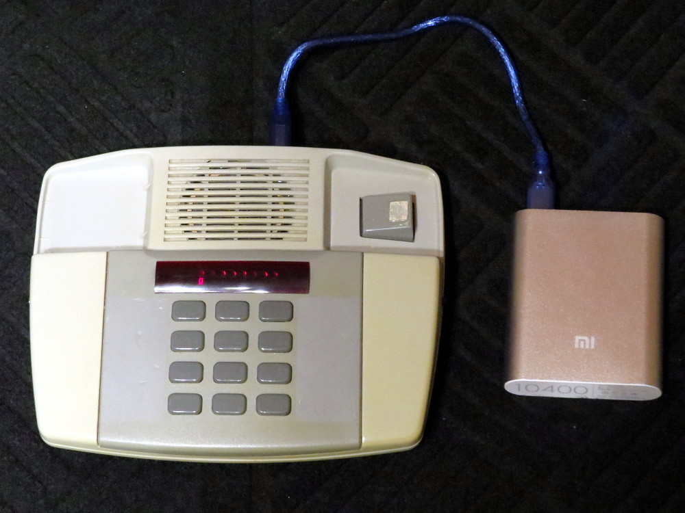
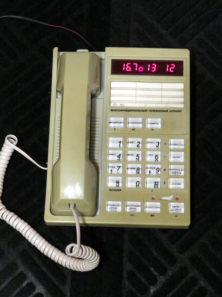
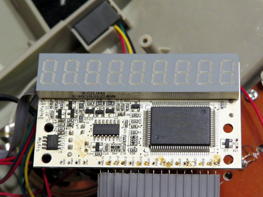
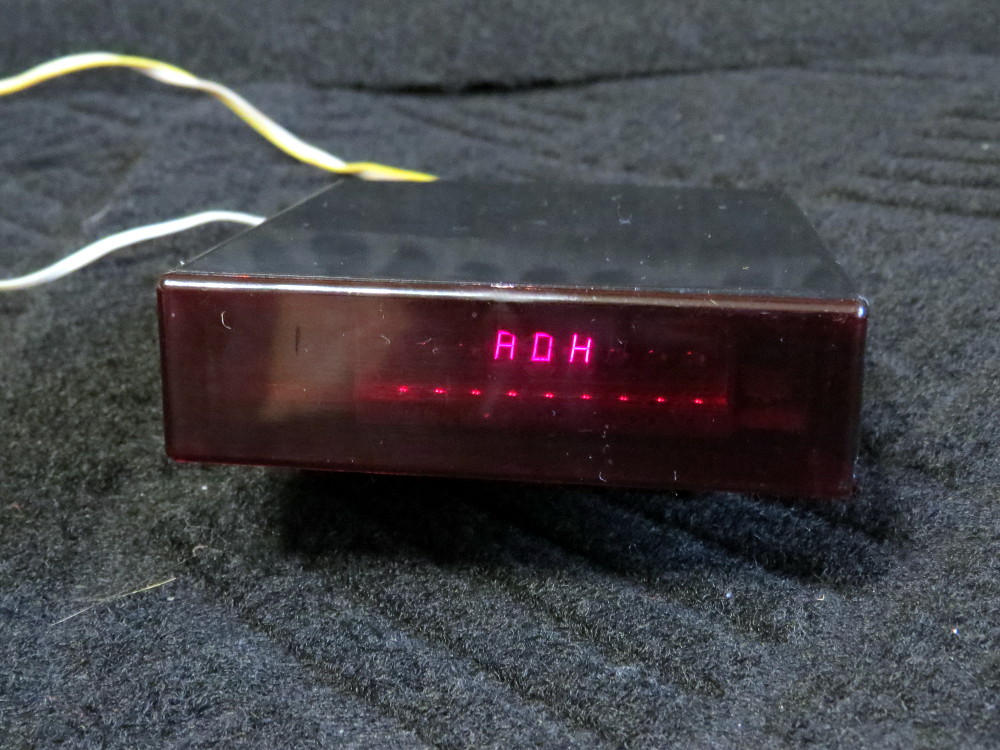
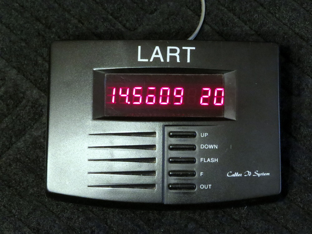
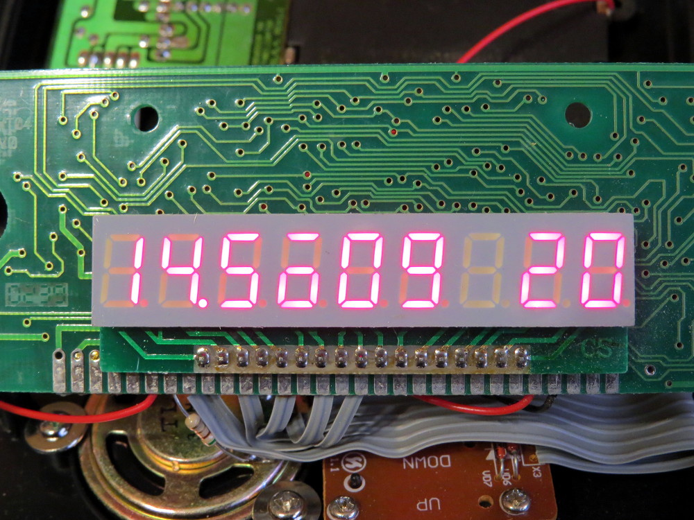
Then it tests LED display and multiplexed display circuit that is also used to poll the keypad matrix, by showing each digit with all segments on, then segment by segment. You can visually see if there is something wrong and get leads to possible source of the issues. From now on test displays pseudo-text messages that specify detected issues.

Then RAM gets tested, 6116 and 6164 supported and detected automatically. At this point test can detect missing CS, RAM degradation, and other memory faults.

Test also checks if the data bus pull up resistor array installed, some firmware versions won't function correctly without it, although some makers were omiting it to reduce the costs.

8253 gets tested next. Issues with control signals, lack of RD signal can be detected. Then 8253-generated interrupt gets tested, so you can see if interrupts is not working.

Test also checks optional configuration diodes (kind of jumpers) that enable expanded keypad and other options in some firmware. I'm stuck at this part at the moment.

A dozen of other hardware checks performed then, ones that related to the analog part, such as if phone line is not connected, incoming call detection, and so one.

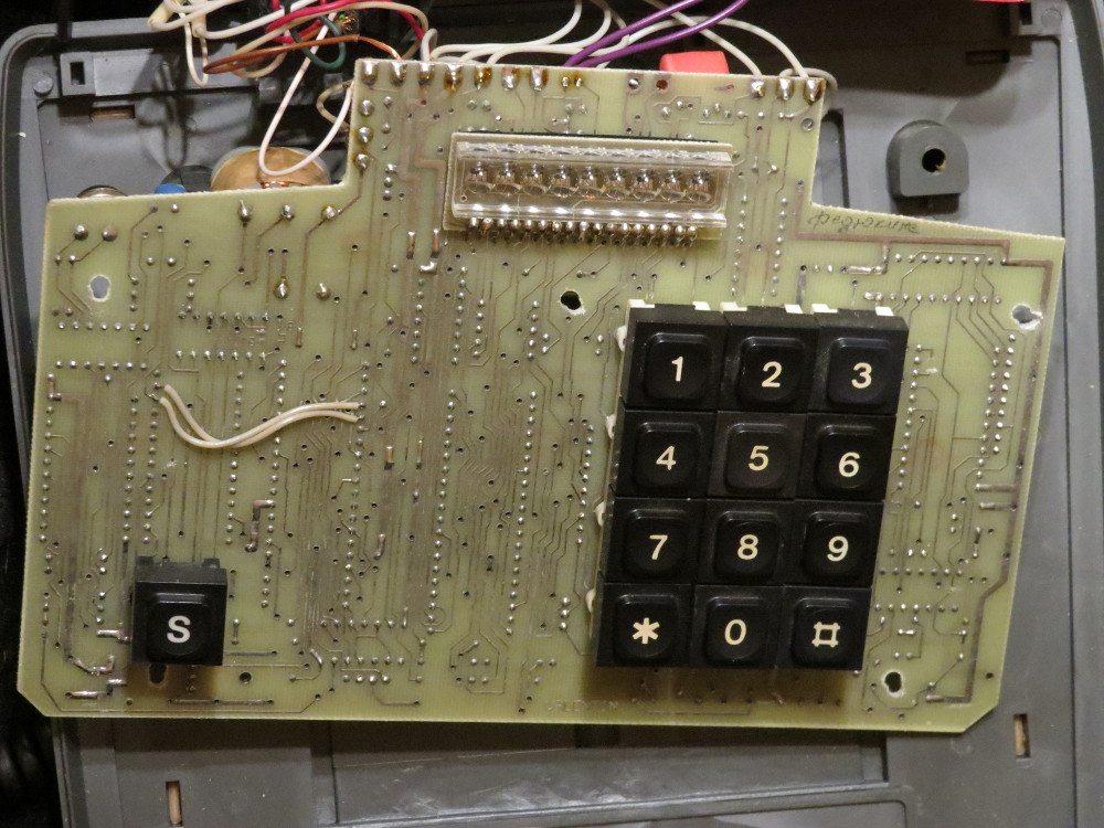
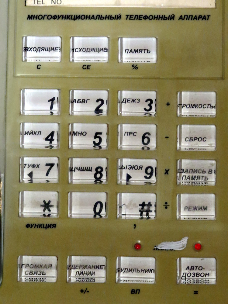
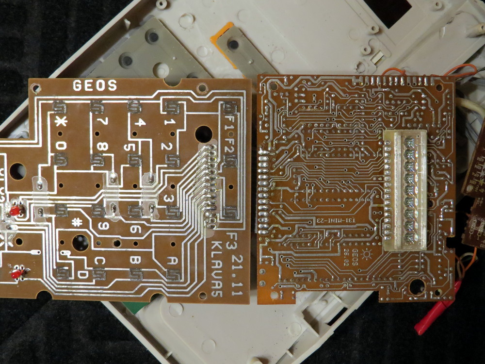
Finally you can test the keypad, either normal 12 button one, or expanded 24/32 buttons - press buttons, and corresponding LED segments will light up. Turned out to be extremely handy, considering a bit tricky matrix layout and multiplexing shared with the display, plus two different layouts for normal and extended keypads.

If this is still not enough, you can then go into 8255 direct control mode. It allows to enable/disable any output line using the keypad, to help you make further HW checks manually.

319

(35 replies, posted in Other Platforms)

Hardware review #4

Another piece of the add-on type of the hardware I just got out of curiosity, for $9.

Very tiny plastic box. Unfortunately, there is not a single button, or speaker, so it does not have controls and does not produce any sound - unless you consider modding, which is easy. Still, makes a very nicely done tiny single board Z80 computer to mod and hack.

The PCB inside is just 8.5x9.5 cm large, with the infamous ALS318 LED display hard mounted to the side. This is a Z80 design, one that is supposedly was used in early Z80 AONs only, no 8253 and 8255 there. Never seen it in full blown phones, though, and this is the first time I actually see it. Judging by the dates on the chips it has been made circa late 1994. I think this is one if not the most cost reduced design, with bare minimum of stuff there.

It has Soviet Z80 clone, one-time programmable 2K ROM that is unfortunately soldered in, no socket there, and somehow original Hitachi's 6116 2K RAM. No buttons means no caller/contact lists to access, so no real use for so much RAM there. Probably it was used just because it was a very common chip easy to obtain, thus cheap.

The firmware called ALFA-3, it displays the name when powered on. Supposedly the device itself also called Elektronika-Alfa-3, but I'm not too sure on this, as there is no labels on the case or board. The functionaliy is also at bare minimum, it just works as Caller ID, absolutely nothing else, not even clock. I also seen other firmware called ALFA, it was 8K large - likely for normal phone, so maybe this 3rd revision is a cut down version of this.


External view. Sorry, it just loves to collect dust.
http://shiru.untergrund.net/temp1/aon_4_1.jpg


The board, fits the case perfectly, no unused space there.
http://shiru.untergrund.net/temp1/aon_4_2.jpg


Close up on the board.
http://shiru.untergrund.net/temp1/aon_4_3.jpg

320

(35 replies, posted in Other Platforms)

Hardware review #3

This device is not to be used in the project, got it for $6 just out of curiosity, as I've seen a lot of similar devices in the same exact case, but with different names and marks. Turned to be very interesting indeed. An add-on AON unit called Lart-201p from December 2002, compact design of the end of era.

A very small device, can be powered from the wall adapter or 3 AA batteries, has the usual 80C31 architecture (for the most part), quite good speaker, and a cut down version of the usual Rus firmware. Actually could easily be a totally portable 1-bit music box or something, but unfortunately this late design uses all SMD parts, the ROM is one-time programmable and has no socket. The parts now is all Chinese imports - by the time it became much more accessible and cheaper, so not a single Soviet made part there.

The most fun and major difference in this particular version of architecture is that it uses serial Flash memory chip 24C16 (2Kx8) instead of the usual 6116 SRAM. As the device functionality does not suppose very frequent information changes (incoming calls list, phone book), it neiter needs much speed nor too many write cycles. Although the endurace of the chip is 1M cycles and it supposed to last really long, there were talks that the modified firmware works very inefficiently and doing lots of unnecessary writes, so the chip got worn out after 2 years of normal use, and had to be replaced.


External view.
http://shiru.untergrund.net/temp1/aon_3_1.jpg


Back side, the AA batteries compartment is there.
http://shiru.untergrund.net/temp1/aon_3_2.jpg


The inside, it has three boards - the main one, 5-button keypad one, and sockets one (not seen on the photo).
http://shiru.untergrund.net/temp1/aon_3_3.jpg


The main board with the main chips marked.
http://shiru.untergrund.net/temp1/aon_3_4.jpg


Close up on the 80C32 and 24C16. Small chip on the bottom left is sound amplifier.
http://shiru.untergrund.net/temp1/aon_3_5.jpg


Finally the large display. You can see it often in 80C31 designs.
http://shiru.untergrund.net/temp1/aon_3_6.jpg

321

(35 replies, posted in Other Platforms)

Hardware review #2

This is another phone I got recently, by the same price of $9. This time it is the 80C31 design example, one I have never seen before actually, but the schematics seems to be typical. It called GEOS-RUS, with GEOS being a small company that produced AONs since mid 90s. I guess the firmware (Geos Rus-20) has been modified by them to their design. It came with the manual and guarantee card that mentions it has been made May 7th 1996 and sold May 15 1996 - probably the most hot sales time it was. Crazy enough, the manual also mentions a government-issued telecommunication certificate of some sort. Well, lots of weird things were possible in Russia of 90s.

Build quality is much better than the previous example. At least it has some screws. But more interestingly, it has main PCB and keypad PCB both designed specifically for this phone model (Technica 2308, a Panasonic clone), probably because it was popular and they had a large supply of these. It still contains the original phone board as well, with most components removed and the rest only being used as mic/speaker amplifiers - common approach in AONs in general. Another unusual thing is that it still uses the old ALS318 LED display, rigidly hardwired to the bottom of the main board, while most of 80C31 designs use much better and larger displays imported from China.


External view.
http://shiru.untergrund.net/temp1/aon_2_1.jpg


Internal view. At first glance the usual mess, but now that's mostly about wires.
http://shiru.untergrund.net/temp1/aon_2_2.jpg


The main AON board is hidden under the original phone main board and actually well fit into the space and screwed to the original points. See how lots of components were removed from the old board, including the main chip.
http://shiru.untergrund.net/temp1/aon_2_3.jpg


The new system board.  You can easily see why they moved to the 80C31 design eventually. Less chips makes it even smaller than the smallest Z80 one, yet roughly equal in power. I marked the main chips with their Western names again.
http://shiru.untergrund.net/temp1/aon_2_4.jpg


Keypad board is also custom, also well fit into the existing place.
http://shiru.untergrund.net/temp1/aon_2_5.jpg

322

(35 replies, posted in Other Platforms)

Regarding the UV EPROMs. As far as i know, Soviet electronics production only managed to get 8K done with reasonable yield. To my knowledge, no UV ROM chips has been released with 16K or more - anything of this capacity in Soviet stuff were mask ROMs or imports. For things like ZX clones Z80 and ROMs had to be imported, and that was very difficult at first. Thus in early stuff such as first ZX clones you can see either 8 of 2K UV ROMs or 2 8K UV ROMs to get the required 16K. Later importing get easier, but prices on local made components were still lower, so in early post-Soviet things like AONs you'll likely will find cloned CPU (sometimes original, though), but ROMs always will be imported. Spectrums were made in large quantities, so a mask ROM with Didactic Scalica firmware was made and used eventually, but AONs were product of individuals and small groups, so it always remained to be using UV EPROM.

323

(35 replies, posted in Other Platforms)

Hardware review #1

This is the first of a few phones I got recently for the project. Seems that it has been made circa 1994. The board is the small Z80 universal one, the most recent parts on the board is from 1993. It has Rus 10 firmware installed, which has been released in late 1994. The build quality is the worst case scenario. Not a single screw or even termoglue to hold the stuff together. The speaker and display were glued to the plastic, but fell off, so when I disassembled it, everything pretty much fell apart. Yet it still in fully working condition!

Is it is in the worst shape, I decided to use it as the main testbed and modded it a bit later, fixed the stuff inside the case, added standard USB socket to power it from a modern power source (nearly all AONs use external 5V adapters with 7805 inside), and other connectors. ZIF socket to be installed yet, will show final mods eventually. For now the photos just show how it was originally.


External view
http://shiru.untergrund.net/temp1/aon_review_1_1.jpg


The 7-segment LED display, shows the idle mode with current time. That square between the numbers displays the current operation mode (can be other figures, this is default), so you can immediately recognize it is Rus firmware.
http://shiru.untergrund.net/temp1/aon_review_1_2.jpg


Internal view
http://shiru.untergrund.net/temp1/aon_review_1_3.jpg

Very simple Z80 computer it is, he said.
http://shiru.untergrund.net/temp1/aon_review_1_4.jpg


Believe or not, it works!
http://shiru.untergrund.net/temp1/aon_review_1_5.jpg


The infamous ALS318 LED display. Soviet-made, and I think it is not a clone (like most of Soviet electronics) - at least I never found the original part. The digits are extremely tiny (1.5x2.5mm), each has individual plastic lens to make them appear bigger. They're always red, no other colors.
http://shiru.untergrund.net/temp1/aon_review_1_6.jpg


The small Z80 board, common revision. I marked main chips with their normal Western names.

Z80 on this board is a weird beast. It is a CMOS version. As far as I know, this one was actually has been made to be used in ZX clones specifically, alongside the ZX ULA clone, yet the latter never come to fruition. This way it got the 1582 number, chip series that otherwise contains all custom ULA-based ASICs, as well as -100 after the part number, which is supposed to be the firmware version (makes sense for ULAs, makes no sense for CPU). It is also marked as KM which means ceramics package, yet it is plastic. Early 1990s were lots of fun for the post-Soviet electronics industry.
http://shiru.untergrund.net/temp1/aon_review_1_7.jpg

324

(35 replies, posted in Other Platforms)

The sound

One interesting topic to discuss is what has been done already in regards to the sound in these devices. Music was relatively important there, used as ring and alarm tones. At first it was all monophonic 8253-driven square wave, as you could hear in the videos linked above, but later (past Z80) designs actually got polyphony and better sound.

At first the sounds range that AONs were capable of consisted of:

- Single channel sound cues and melodies
- One bit voice samples
- DTMF signals for tone dial

As far as I know, no one tried to do 1-bit synthesis for more complex music timbres and/or polyphony on the original hardware, although you can be sure a lot could be achieved there (and that's the goal of my project), especially considering hardware PWM possibility.

With the advent of 80C31 based AONs, sound started get more advanced. At first it was still one channel square wave, but with arpeggios and stuff (Rus 27). I think the CPU power of 80C31 at 10-12 MHz is roughly equivalent to Z80 at 4 MHz, maybe a bit better, but totally different architecture creates an interesting field for experiments with 1-bit synthesis.

Now, if you somehow get tired of 1-bit and want to try something different, there is more worth to mention.

Circa 2003 people from the Rus firmware devs, now turned into Rus Telecom company, managed to get 80C51-based MCU ASIC into production at Taiwan, called R100-XP. It has been designed specifically to be used in their AONs, with most of required interfaces built-in, and the most interesting feature of it was on-die AY-3-8910 replica. Phones based on this MCU, like Rus 28 Sonata, actually contained 1990s ZX Spectrum demoscene music! It sounds just like the real thing. Unfortunately, these phones are kind of rarity and hard to obtain, as they were produced and sold at decline of the AONs popularity.

There is another Rus 28 Sonata phone as well, likely with different board revision yet the same basic firmware, that besides the AY replica has 6 channel polyphonic music with more complex timbres. I don't have much info on this, but it sounds on par with the early polyphonic cell phones, and the sound is likely produced by some MIDI chip. Maybe VS1033 (was popular back then) or something.

325

(35 replies, posted in Other Platforms)

The tech

Now let's see what these things got inside.

The 8080-based design is a rarity, because the CPU required three power voltages, was relatively slow and complex, so it was quickly replaced with a Z80 design. Thus I won't go into specifics with that one. Then there was an early Z80-based design without 8253, it is even more obscure than 8080 designs.

The most common Z80-based design has:

- Z80 running at 4 MHz. No wait states, NMI not used.
- 8253 running at 1 MHz, one channel for INT, another for sound output.
- 8255 to control display and poll buttons.
- 9-digit 7-segment LED driven by a parallel register and 8255.
- 2K SRAM, could be 8K. The 2K is most commonly installed, direct 8K installation used to be done to expand contact lists capacity. Schematics is designed for 8K, no banking. RAM can be battery backed, usually there is a capacitor large enough to keep the contents of the RAM if the device gets powered off for a minute.
- Up to 64K ROM, the usual size is 32K that fits as a whole into the address space. In case with 64K extra 32K is banked using an 8255 output line.
- Up to 7x8 key matrix, at least 12 standard keys connected, depends on phone model.
- All I/O devices conviniently mapped to the Z80 I/O space with short addressing, no memory mapped devices there.
- It even has port to start/stop tape recorder, to be used as an answering machine.

Thinking of it, it is quite a 1-bit power house. Slightly faster than ZX Spectrum, no wait states at all, fast access to all I/O, 8253 use is very similar to the one found in IBM XT, can be used for PWM and stuff. You also can control output directly with additional output bit, as well as with gate control. There is enough outputs to make stereo, or multiple outputs with analog mixing. There is a comparator that is used to sample the phone line to read Caller ID codes (a series of sine waves, frequency encoded), which is very similar to the tape interface.

The main challenges there is very limited RAM, although with 8K it gets better, and techically you can put 32K there using extra 8255 lines to control paging, and the limited user interface capabilities, especially in regards of the display. But it is also more fun then.

Interesting thing to note is that as there is no TV display and its specific timings, you can easily downclock or overclock the device just by changing the crystal oscillator. Of course it would break the original phone firmware functionality (needs to run at specific clock to detect and generate phone signals), but totally no problems for new custom firmware. The limit is the just the frequency that main chips can tolerate. Normally there is original Z80A or a CMOS clone installed that works on the standard 4 MHz and can tolerate a little bit more.


The 80C31 designs is relatively common, but not nearly as much as Z80 one. There is a number of designs. I'm not really want to work with these at the moment, so I won't get far into specs, but in short it is:

- 80C31 at 10/12 MHz
- Up to 64K ROM, usually 32K
- 2K or 8K SRAM
- No 8253 or 8255, just a few latches for I/O lines


Besides the full blown phones, there were Caller ID add-ones. They're include the same variety of the hardware and more, i.e. Z80 and 80C31 designs. The firmware is usually very similar, kind of cut-down versions of the bigger brothers, but controls are much simpler, usually just five buttons. These can be interesting too, but for now I leave them out.

Should be also mentioned that there were other more modern designs, not listed above, PIC based for example. These mostly were done as add-on devices.


Just for reference, Z80 design schematics:

http://shiru.untergrund.net/temp1/aon_z80_schematics.gif